Microwave pyrolysis equipment

A kind of equipment and pyrolysis technology, applied in the field of microwave pyrolysis equipment, can solve the problems of low processing efficiency, small capacity, low power, etc., and achieve the effects of uniform heating, simplified structure and guaranteed effectiveness

Pending Publication Date: 2020-05-12
北京诺芯环境科技有限公司
View PDF0 Cites 1 Cited by
  • Summary
  • Abstract
  • Description
  • Claims
  • Application Information

AI Technical Summary

Problems solved by technology

[0004] The microwave pyrolyzer in the prior art has a small capacity and low power, and can realize the pyrolysis of small batches of materials. For the pyrolysis of large batches of materials, it often needs to be carried out in multiple times, and the processing efficiency is low.

Method used


Image

  • Microwave pyrolysis equipment
  • Microwave pyrolysis equipment
  • Microwave pyrolysis equipment

Examples


Embodiment 1

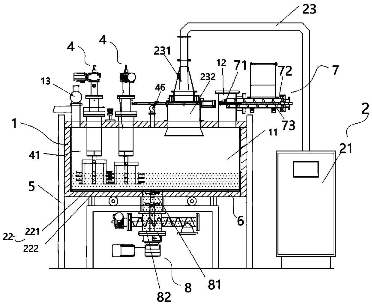
[0066] A kind of pyrolysis equipment is recorded in the embodiment of the present invention, and this pyrolysis equipment utilizes microwave heating to carry out pyrolysis treatment to material, as figure 1 , figure 2 , image 3 , Figure 4 , Figure 5 , Image 6 As shown, the pyrolysis equipment includes a housing 1, a microwave generating device 2, a waveguide protection device 3, and a stirring device 4, wherein the housing 1 is arranged on a frame 5, and inside the housing 1 there is a The housing cavity 11 is also provided with a housing air inlet 12 on the housing 1 for introducing safety gas, and a housing gas outlet 13 for discharging waste gas or other gas mixtures generated after pyrolysis reaction, The material undergoes a pyrolysis reaction inside the containing cavity 11, and the microwave generating device 2 transmits microwaves to the inside of the containing cavity 11. Specifically, the microwave generating device 2 includes at least one microwave generato...

Embodiment 2

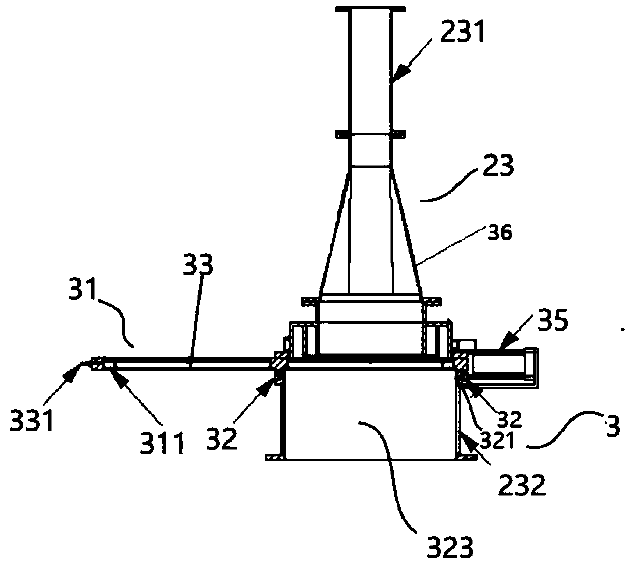
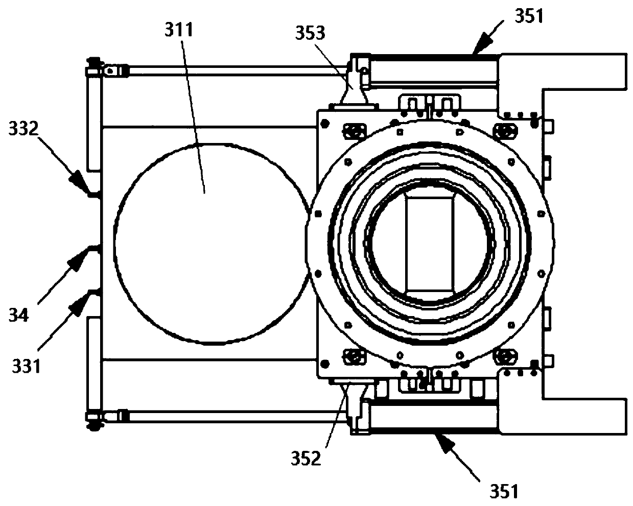
[0091]This embodiment provides a microwave pyrolysis device. Compared with the microwave pyrolysis device provided in Embodiment 1, the difference is that in this embodiment, the barrier assembly 31 includes two layers of barriers 311, a sealed cavity 33 is formed between the two layers of barriers 311, the first barrier 311 connected to the waveguide cavity in the second waveguide 232 is provided with at least one through hole, and the two layers of barriers 311 The gap between them is the import channel 32, and the through hole is used as the import outlet port 321, and the protection medium is passed into the inside of the sealed cavity 33, and the protection medium is input to the waveguide along the through hole on the first barrier member 311 as an outlet. Inside the chamber, by changing the way the protective medium is fed into the dielectric protection layer 323, the oxidation reaction with the carbon-containing mixture in the dielectric protection layer 323 and the car...

Embodiment 3

[0095] This embodiment provides a microwave pyrolysis device, which differs from the microwave pyrolysis devices provided in Embodiment 1 and Embodiment 2 in that, in this embodiment, it can be placed inside the body of the housing 1 An insulating layer 6 is provided, and an insulating material is filled into the insulating layer 6, so that when the material in the containing cavity 11 undergoes a pyrolysis reaction, the heat exchange between the containing cavity 11 and the outside can be reduced, and the pyrolysis reaction can be ensured to proceed smoothly , in this embodiment, the insulation material material can be thermal insulation cotton, of course, it can also be insulation material of other materials, as long as it can withstand high temperature, does not absorb microwaves, is non-flammable, and has good thermal insulation performance, so as to reduce the occurrence of material in the cavity and the outside. Just heat exchange.

[0096] In this embodiment, a galvaniz...


PUM


Abstract

The invention relates to the technical field of pyrolysis, and provides pyrolysis equipment. The equipment comprises a machine frame, a shell, a microwave generating device, a waveguide protection device and a stirring device, wherein the shell is arranged on the machine frame, and a containing cavity used for containing materials is formed in the machine frame; the microwave generating device comprises at least one microwave generator and a wave absorbing assembly, the microwave generator is communicated with the containing cavity through a waveguide, and the wave absorbing assembly is arranged in the containing cavity; the waveguide protection device is arranged on the waveguide, and a dielectric protection layer is formed between the containing cavity and the waveguide; the stirring device is arranged on the shell, and one end of the stirring device extends into the containing cavity and is inserted into the material for stirring. The pyrolysis equipment is reasonable in structuraldesign, pyrolysis treatment can be carried out on a large batch of materials, all the devices operate independently, maintenance is convenient, the treatment efficiency is high, and the defect that the large batch of materials need to be treated in batches is overcome.

Description

technical field [0001] The invention relates to the technical field of reaction equipment, in particular to a microwave pyrolysis equipment. Background technique [0002] The principle of microwave heating technology is: when the medium to be heated is placed in the microwave electromagnetic field, the polar molecules and non-polar molecules in the medium material will form dipoles or rearrange the existing dipoles. As the high-frequency alternating electromagnetic field swings at a speed of hundreds of millions of times per second, it is necessary to overcome the interference and obstacles of the original thermal motion of the molecules and the interaction between the molecules. Therefore, an effect similar to friction will be produced, making the electromagnetic It can be gradually converted into heat energy, so that the temperature of the medium can be greatly improved. [0003] Compared with traditional fossil energy heating technology, microwave heating technology has ...

Claims


Application Information

Patent Timeline
Patent Type & Authority Applications(China)
IPC IPC(8): C10G1/00C10G1/10C10B53/07C10B53/00
CPCC10B53/00C10B53/07C10G1/00C10G1/10Y02P20/143
Inventor 刘俊祥孔庆锋刘强曹春峰吴宗博
Owner 北京诺芯环境科技有限公司
Why Eureka
Try Eureka