
Ultrasonic interference phenomenon demonstration and sound velocity measurement device

A measuring device, ultrasonic technology, applied in measuring devices, measuring ultrasonic/sonic/infrasonic waves, measuring propagation speed and other directions, can solve the problems of personnel errors, difficult to accurately distinguish straight line segments and extremely flat ellipses, etc., and achieve personnel errors. Small, simple structure, easy to operate

Pending Publication Date: 2020-05-12
INST OF DISASTER PREVENTION
View PDF0 Cites 2 Cited by
  • Summary
  • Abstract
  • Description
  • Claims
  • Application Information

AI Technical Summary

Problems solved by technology

The phase difference can be determined by observing the Lissajous figure synthesized by the vertical vibration of the transmitted wave and the received signal on the oscilloscope, and then the wavelength can be determined according to the periodic change of the Lissajous figure; since the scanning display line on the fluorescent screen of the oscilloscope has a certain width, resulting in very It is difficult to accurately distinguish between a straight line segment and an extremely flat ellipse, so it is easy to cause large personnel errors when judging whether the phases of two vibrations are the same (or opposite) based on the Lissajous figure

Method used


Image

  • Ultrasonic interference phenomenon demonstration and sound velocity measurement device
  • Ultrasonic interference phenomenon demonstration and sound velocity measurement device
  • Ultrasonic interference phenomenon demonstration and sound velocity measurement device

Examples


Embodiment Construction

[0039] In order to facilitate the viewing of the various reference signs in the drawings of the specification, the unified description of the reference signs appearing in the drawings of the specification is as follows:

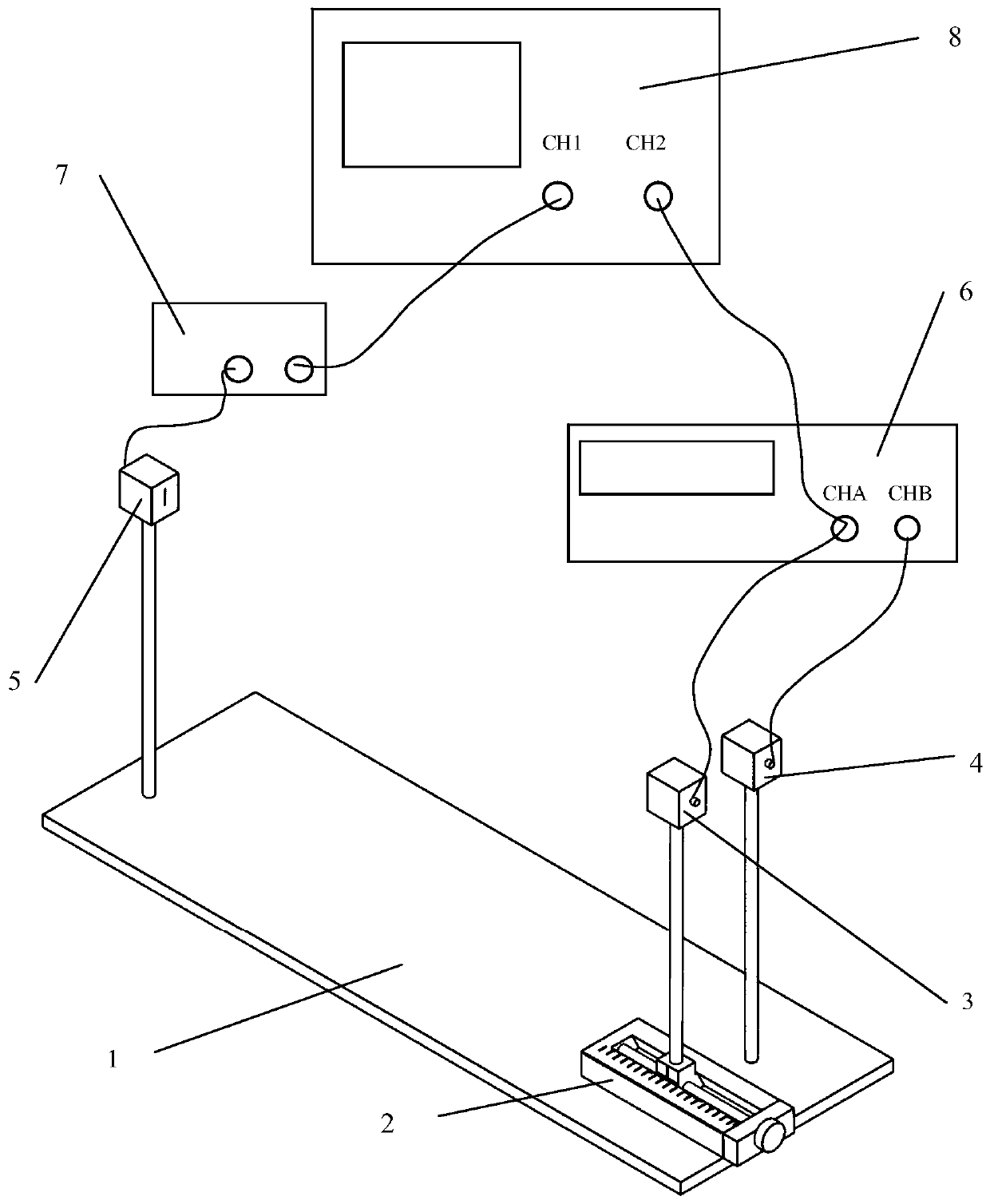
[0040] figure 1 and Figure 5 Middle: 1 is the platform; 2 is the linear translation platform; 3 is the mobile transmitting transducer assembly; 4 is the fixed transmitting transducer assembly; 5 is the receiving transducer assembly; 6 is the signal generator; 7 is the signal amplifier; 8 It is a dual-trace oscilloscope.

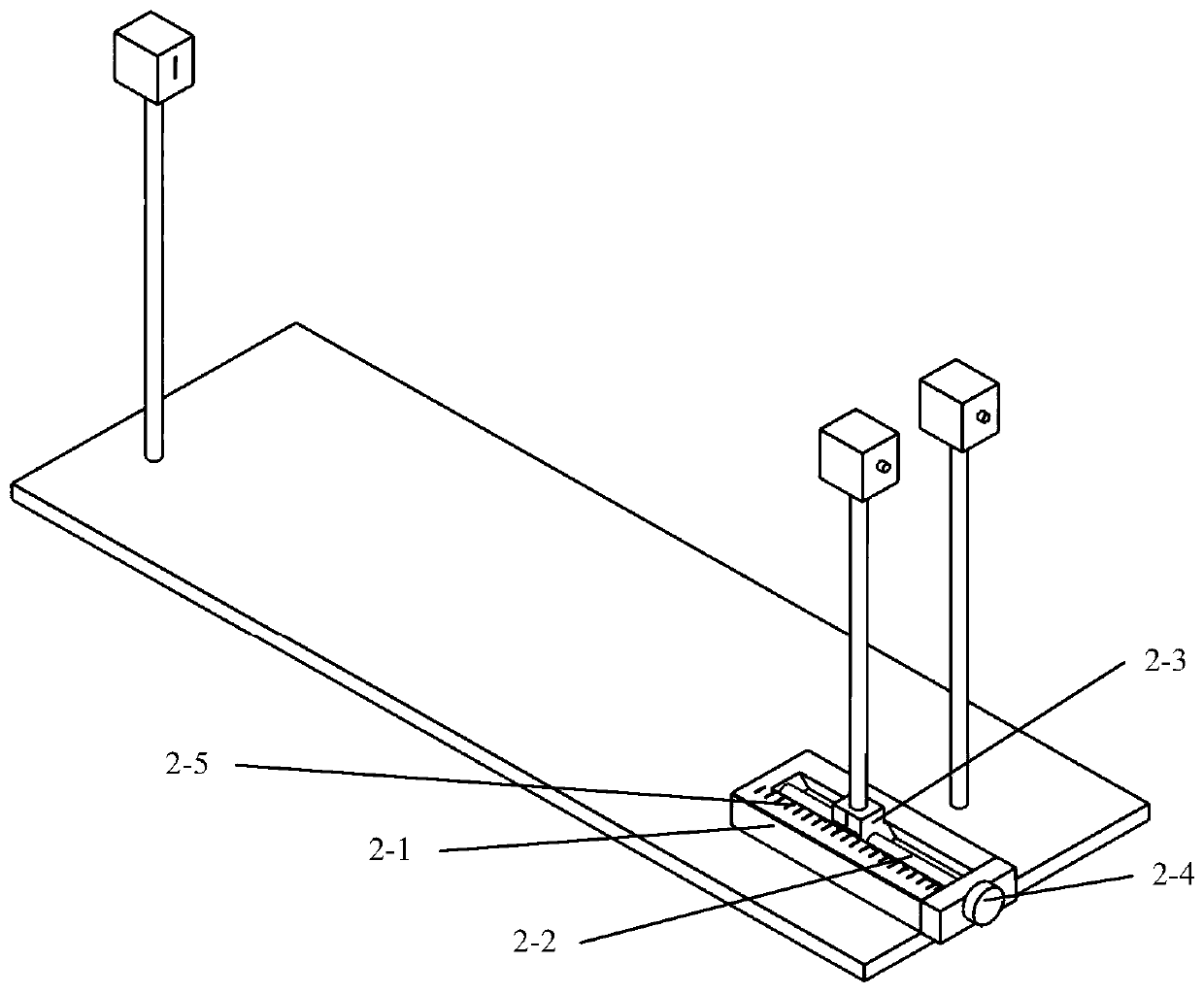
[0041] figure 2 Middle: 2-1 is the frame; 2-2 is the screw; 2-3 is the slider; 2-4 is the micrometer drum; 2-5 is the scale.

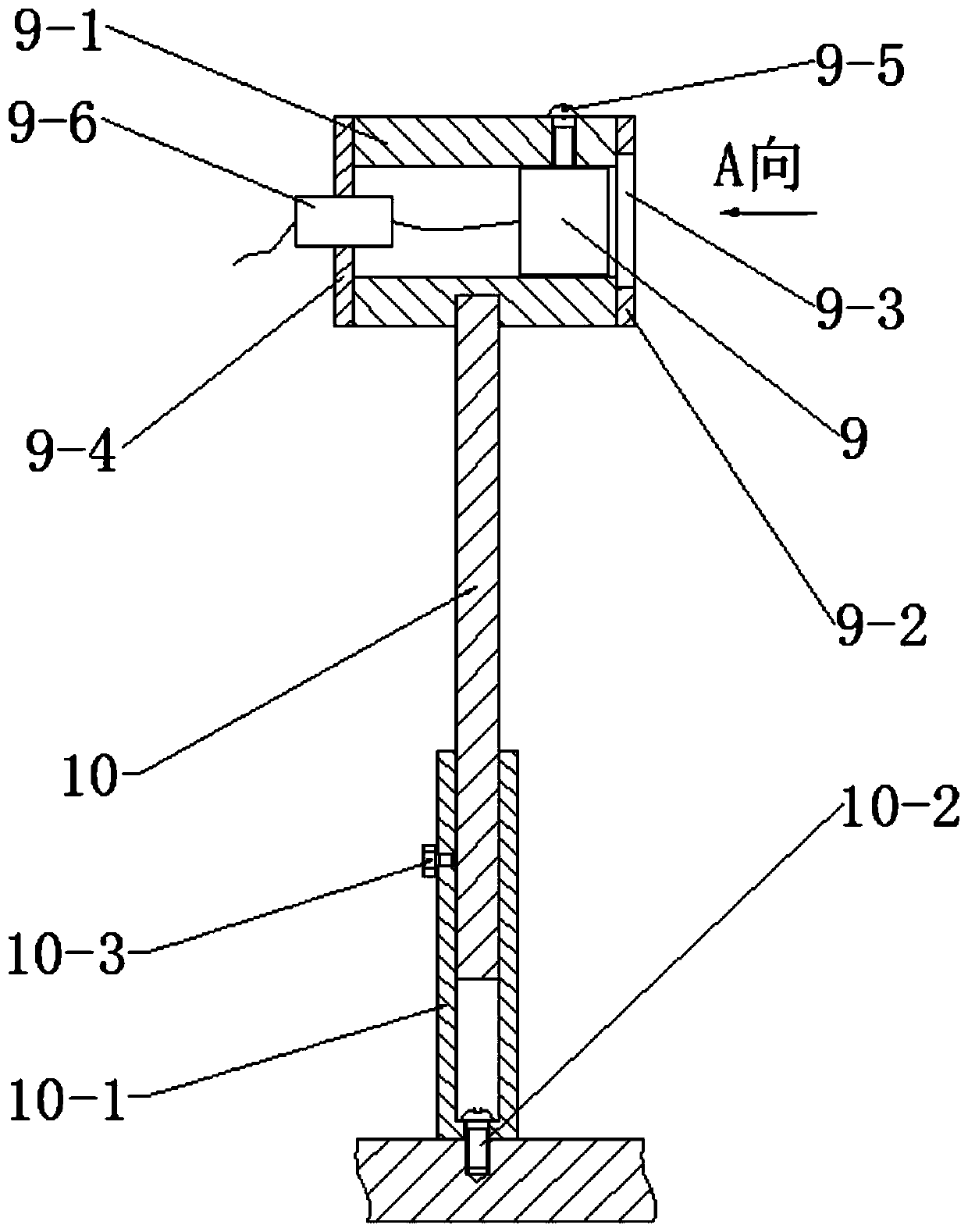
[0042] Figure 3 to Figure 4 Middle: 9 is the transducer; 9-1 is the body; 9-2 is the front cover; 9-3 is the slit; 9-4 is the back cover; 9-5 is the fastening screw; 9-6 is the socket; 10 10-1 is a sleeve; 10-2 is a sleeve fixing screw; 10-3 is a locking knob of a vertical rod.

[0043] The present invention...


PUM

PropertyMeasurementUnit
Widthaaaaaaaaaa

Abstract

The invention discloses an ultrasonic interference phenomenon demonstration and sound velocity measurement device. The device comprises a platform, a linear translation platform, a mobile transmittingtransducer assembly, a fixed transmitting transducer assembly, a receiving transducer assembly, a signal generator, a signal amplifier and a double-trace oscilloscope. Each transducer assembly comprises a transducer, an installation base and a vertical rod, the vertical rod is fixedly connected to the lower portion of the installation base, the installation bases are provided with slits, and thetransducers are arranged right opposite to the slits. The signal generator excites the transducers in the mobile transmitting transducer assembly and the fixed transmitting transducer assembly to generate ultrasonic waves, and the ultrasonic waves are emitted through the slits to form two independent ultrasonic transmitting sources. And the two columns of transmitted waves are superposed when being transmitted to the slit of the receiving transducer assembly. The device is simple in structure and convenient to operate; the ultrasonic interference phenomenon can be demonstrated visually; the wavelength and sound velocity of the ultrasonic interference can be measured accurately; and the ultrasonic interference phenomenon demonstration and sound velocity measurement device can also be used for demonstrating and observing the beat frequency phenomenon.

Description

technical field [0001] The invention relates to a university physics teaching experiment instrument, specifically a device for measuring wavelength and wave velocity by using an ultrasonic interference method, and belongs to the technical field of physical experiment measurement. Background technique [0002] The propagation of sound waves is closely related to the properties and state of the medium, and the change of the physical properties and state of the medium can be detected by measuring the sound velocity in the medium. The measurement of the speed of sound is an important content in the teaching of college physics experiments. At present, the methods for measuring sound velocity mainly include: standing wave method (resonance interference method), phase comparison method, Doppler effect method and time difference method; among them, standing wave method and phase comparison method are the most typical, the core of these two methods Both measure the wavelength of the...

Claims


Application Information

Patent Timeline
IPC IPC(8): G01H5/00G09B23/14
CPCG01H5/00G09B23/14
Inventor 闫志涛许德飞谭覃敬天慧
Owner INST OF DISASTER PREVENTION
Learn More