Material surface anti-cavitation performance test method based on laser driving

A laser-driven, anti-cavitation technology, used in the analysis of materials, strength characteristics, testing wear resistance, etc., can solve the incompatibility of the service conditions of the steam turbine unit, it is impossible to simulate the cavitation effect and activation effect of the last stage blade of the steam turbine, It is impossible to comprehensively evaluate the anti-cavitation performance of blade materials, so as to achieve the effect of realistic simulation environment and strong data reliability.

Active Publication Date: 2020-05-12
ZHEJIANG UNIV OF TECH
View PDF9 Cites 0 Cited by
  • Summary
  • Abstract
  • Description
  • Claims
  • Application Information

AI Technical Summary

Problems solved by technology

The above test equipment and means can only realize the test of the effect of a single gas or liquid drop on the material, but cannot comprehensively evaluate the anti-cavitation performance of the blade material in the actual working condition
[0005] In addition, during the actual service process of the last stage blade, when the bubbles existing in the liquid phase collapse, the high-temperature and high-pressure micro-jet is released instantaneously within microseconds to nanoseconds, causing severe cavitation on the surface of the material effect and activation effect, and the patent: "A Material Cavitation Resistance Test System" (Application Publication No.: CN 106323851 A, Application Publication Date: 2017.01.11) is impossible to simulate only by high-pressure water nozzles and high-pressure gas nozzles The cavitation effect and activation effect of the final stage blades of the steam turbine in the actual service process are not consistent with the actual service conditions of the steam turbine unit

Method used


Image

  • Material surface anti-cavitation performance test method based on laser driving
  • Material surface anti-cavitation performance test method based on laser driving

Examples


Embodiment Construction

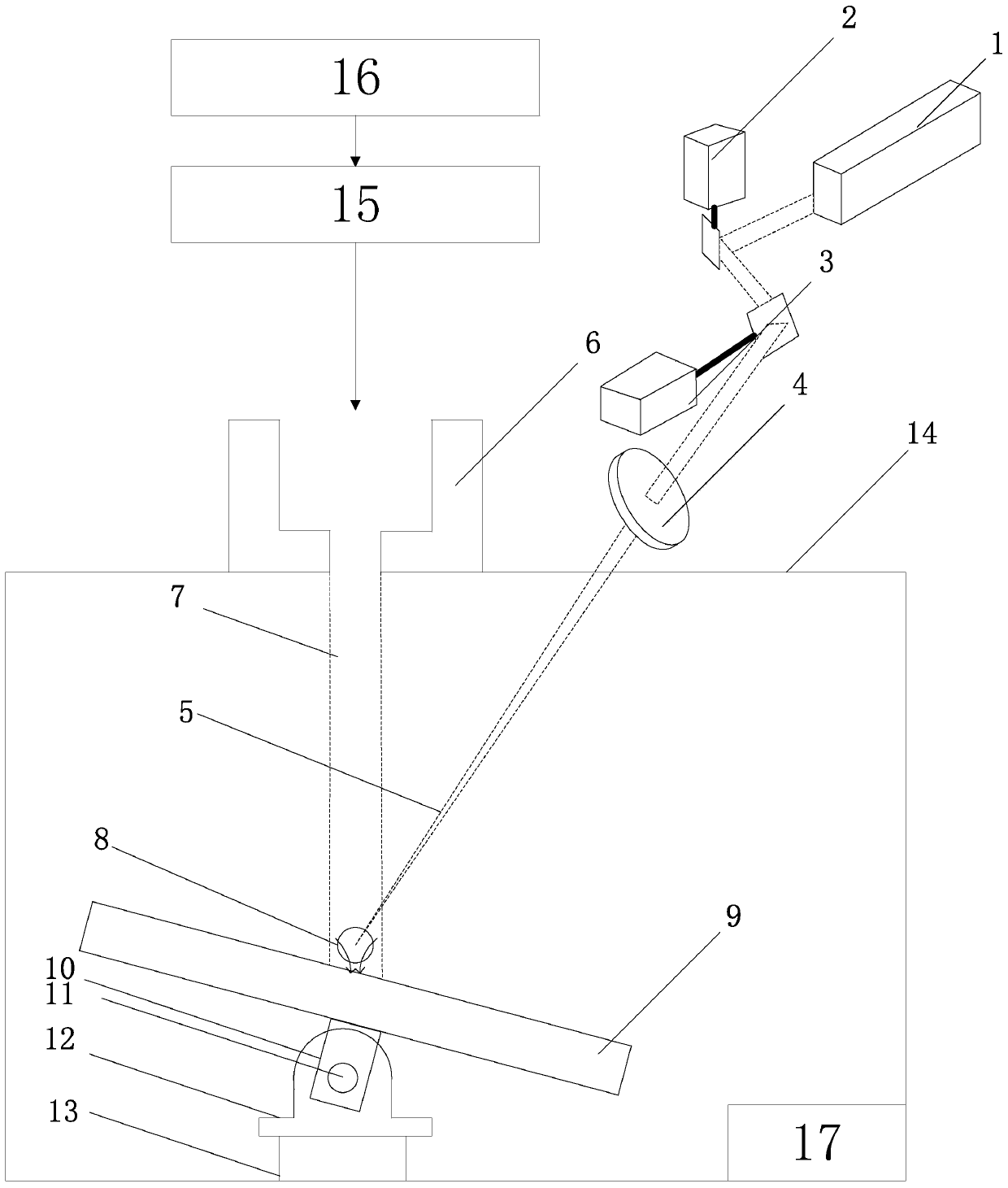
[0021] Further illustrate the present invention below in conjunction with accompanying drawing.

[0022] A method for testing the anti-cavitation performance of a material surface driven by a laser, comprising the steps of:

[0023] (1) When the test starts, the sample 9 to be tested is fixed on the clamp 10, and the spatial position and the angle of inclination of the clamp 10 are adjusted to change the spatial position and the angle of inclination of the sample to be tested 9.

[0024] (2) Add specified water body to the water tank 16, and use the magnetic stirrer at the bottom of the water tank 16 to stir the water body. After the water body is stirred until uniform, the water jet 7 is generated by the high-pressure water generator 15 and ejected to the test sample 9 surface to generate water hammer and shock waves.

[0025] The water body can be distilled water, deionized water, tap water, distilled water with microparticles, deionized water with microparticles, tap water...


PUM

PropertyMeasurementUnit
particle diameteraaaaaaaaaa

Abstract

The invention discloses a material surface anti-cavitation performance test method based on laser driving, which comprises the following steps of: 1) fixing a to-be-tested sample on a clamp, and adjusting the spatial position and the inclination angle of the clamp, 2) adding the water body into a water tank, stirring the water body by using a magnetic stirrer until the water body is uniformly stirred, generating water jet by using a high-pressure water generator, and ejecting the water jet to the surface of the to-be-tested sample to generate a water hammer effect and a shock wave effect, and(3) starting a laser light source of the laser, and enabling laser pulse energy to act in the water jet above the to-be-tested sample so as to generate local high temperature, so that liquid in a laser spot generated by laser focusing is instantly vaporized to form bubbles. Bubbles grow up and collapse in water jet, high-temperature and high-pressure micro-jet is released instantly, and a violentcavitation effect and an activation effect are generated on the surface of a to-be-tested sample. Thus, liquid drop impact waves, water hammer effects, cavitation effects and activation effects can beconsidered, and the anti-cavitation performance of the to-be-tested sample can be comprehensively reflected.

Description

technical field [0001] The invention belongs to the technical field of cavitation resistance evaluation of materials, and in particular relates to a method for testing the cavitation resistance performance of material surfaces. Background technique [0002] During the actual service process, the last stage blade of the steam turbine is subjected to cavitation by the wet steam containing water droplets and fine particles for a long time. Secondary water droplets entrained in the steam flow hit the running final blade at high speed, which will cause honeycomb-shaped defect tissue on the edge of the blade, especially the top of the steam inlet side and the root of the steam outlet side of the blade, and then form a large number of tiny cracks. As a result, the anti-fatigue performance of the blade is reduced, thereby changing the vibration characteristics of the blade, weakening the strength of the blade, and deteriorating the aerodynamic performance of the blade. This deterio...

Claims


Application Information

Patent Timeline
Patent Type & Authority Applications(China)
IPC IPC(8): G01N3/56G01N3/02
CPCG01N3/02G01N3/565G01N3/567
Inventor 姚建华李珏辉王梁
Owner ZHEJIANG UNIV OF TECH
Why Eureka
Try Eureka