Oil seal condensation system for waste tire thermal cracking

A waste tire and condensation system technology, which is applied in the petroleum industry, steam condensation, multi-effect/separation condensation, etc., can solve the problems of incomplete oil and gas condensation and large space occupation, and realize continuous industrial production, ensure oil and gas recovery, Thorough effect of oil and gas recovery

Pending Publication Date: 2020-05-15
QINGDAO EXCEL INTELLIGENT EQUIP CO LTD
View PDF0 Cites 3 Cited by
  • Summary
  • Abstract
  • Description
  • Claims
  • Application Information

AI Technical Summary

Problems solved by technology

The traditional condensing method is to use a coil condensing device, so that the oil and gas pass through the coil, and water is sprayed outside the coil for cooling. The problem of incomplete condensation of oil and gas
In order to reduce the space occupied by the condensing device, at present, tube and tube condensers are usually used to condense the pyrolysis gas of waste tires, but there is still the problem of incomplete condensation of oil and gas

Method used


Image

  • Oil seal condensation system for waste tire thermal cracking
  • Oil seal condensation system for waste tire thermal cracking

Examples


Embodiment Construction

[0017] In the following, the present invention will be specifically described through exemplary embodiments. It should be understood, however, that elements, structures and characteristics of one embodiment may be beneficially incorporated in other embodiments without further recitation.

[0018] In the description of the present invention, it should be noted that the orientation or positional relationship indicated by the terms "inner", "outer", "top", "bottom", etc. is based on the positional relationship shown in the drawings, and is only for the convenience of description The present invention and simplified description do not indicate or imply that the device or element referred to must have a specific orientation, be constructed and operate in a specific orientation, and thus should not be construed as limiting the present invention. In addition, the terms "first", "second", and "third" are used for descriptive purposes only, and should not be construed as indicating or ...


PUM


Abstract

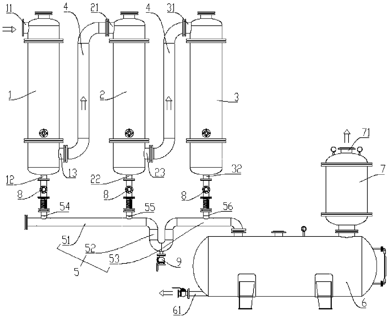
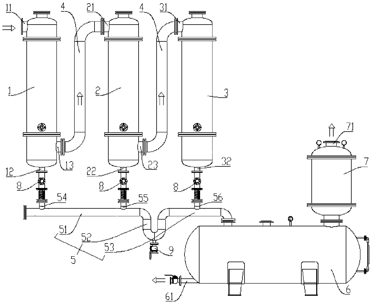
The invention provides an oil seal condensation system for waste tire thermal cracking, which belongs to the technical field of waste tire thermal cracking, and can fully condense gas generated by waste tire thermal cracking. The oil seal condensation system comprises a first condenser, a second condenser and a third condenser, wherein a gas conveying pipeline is connected between a non-condensable gas outlet of the first condenser and a gas inlet of the second condenser, and a gas conveying pipeline is connected between a non-condensable gas outlet of the second condenser and a gas inlet of the third condenser. The oil seal condensation system further comprises an oil conveying pipeline. The oil conveying pipeline comprises a first straight pipe section, a U-shaped pipe section and a second straight pipe section. The first straight pipe section is provided with a first oil product inlet connected with a condensed oil outlet of the first condenser and a second oil product inlet connected with a condensed oil outlet of the second condenser, and the second straight pipe section is provided with a third oil product inlet connected with a condensed oil outlet of the third condenser. The second straight pipe section is connected with an oil product collecting tank, and a non-condensable gas distributing bag is arranged at the top of the oil product collecting tank.

Description

technical field [0001] The invention belongs to the technical field of thermal cracking of waste tires, in particular to an oil seal condensation system for thermal cracking of waste tires. Background technique [0002] The thermal decomposition technology of waste tires is to use the hot flue gas produced by the combustion of various industrial waste oils or use electric heating devices to heat and decompose waste tires in an oxygen-deficient or inert atmosphere, and recover gas, oil, solid carbon, steel wire and some chemical products. Products, wherein the gas (including oil gas and non-condensable gas) generated by thermal cracking needs to be condensed to further recover the oil gas therein. The traditional condensing method is to use a coil condensing device, so that the oil and gas pass through the coil, and water is sprayed outside the coil for cooling. The problem of incomplete condensation of oil and gas. In order to reduce the space occupied by the condensing de...

Claims


Application Information

Patent Timeline
Patent Type & Authority Applications(China)
IPC IPC(8): B01D5/00C10G5/06
CPCB01D5/0033B01D5/0036B01D5/009B01D5/0093C10G5/06
Inventor 刘耀强冷帅邢济尧房海滨薛培青
Owner QINGDAO EXCEL INTELLIGENT EQUIP CO LTD
Why Eureka
Try Eureka