Numerical control milling machine for machining heat exchanger tube partition plates

A technology for CNC milling machines and heat exchanger tubes, applied to milling machines, milling machine equipment, metal processing equipment, etc., can solve problems such as not being able to meet the needs of use, and achieve the effects of strong adjustment ability, improved processing ability, and good flexibility

Inactive Publication Date: 2020-05-19
大冶市志成孔板有限公司
View PDF1 Cites 0 Cited by
  • Summary
  • Abstract
  • Description
  • Claims
  • Application Information

AI Technical Summary

Problems solved by technology

[0002] In the prior art: the patent application publication number CN 107756076A discloses a CNC milling machine, including an operation platform, on which a cleaning groove is installed, and the groove depth direction of the cleaning groove is perpendicular to the table surface of the operation platform and extends toward the bottom surface of the operation platform , the CNC milling machine also includes a fixture assembly, the fixture assembly includes two fixtures arranged at relative intervals, the two fixtures are located in the cleaning tank, and the two fixtures are installed on the operating platform, the fixture includes a fixture main body and a clamping part, and the clamping part is located at The top of the fixture body, and the fixture body is fixedly connected to the fixture body, and the CNC milling machine also includes a milling cutter, the milling cutter is installed on the CNC spindle of the CNC milling machine, and the axis of the milling cutter extends along the table surface perpendicular to the operating platform, however, there is no A CNC milling machine used for processing heat exchanger tube partitions cannot meet the needs of use

Method used


Image

  • Numerical control milling machine for machining heat exchanger tube partition plates
  • Numerical control milling machine for machining heat exchanger tube partition plates

Examples


Embodiment Construction

[0012] The following will clearly and completely describe the technical solutions in the embodiments of the present invention with reference to the accompanying drawings in the embodiments of the present invention. Obviously, the described embodiments are only some, not all, embodiments of the present invention. Based on the embodiments of the present invention, all other embodiments obtained by persons of ordinary skill in the art without making creative efforts belong to the protection scope of the present invention.

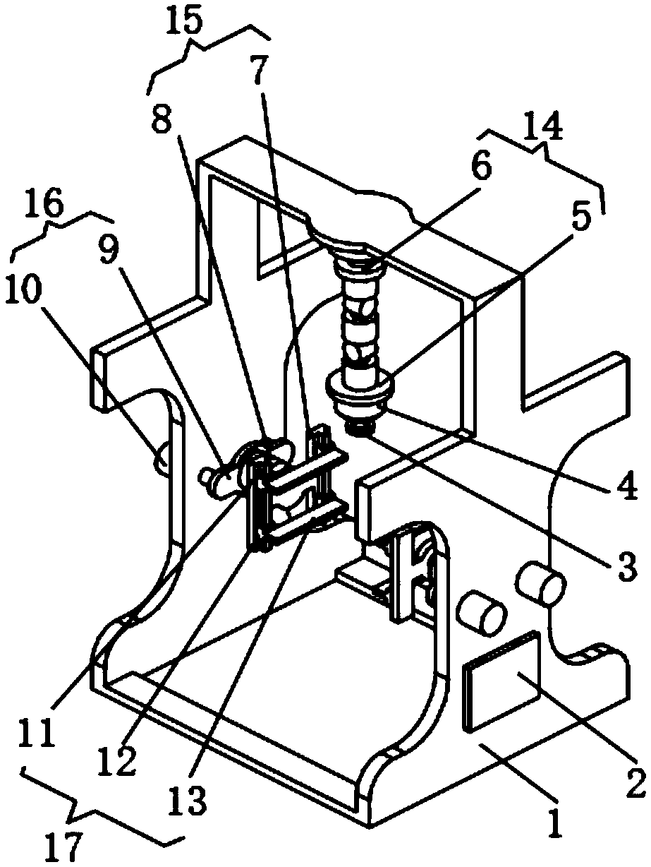
[0013] see figure 1 , the present invention provides a technical solution: a numerically controlled milling machine for processing heat exchanger tube partitions, including a frame 1, an open-source single-chip microcomputer 2 and a telescopic mechanism 16 are respectively installed on the side of the frame 1, and the end of the telescopic mechanism 16 A turning mechanism 15 is installed at the top of the turning mechanism 15, and a clamping mechanism 17 is in...


PUM


Abstract

The invention discloses a numerical control milling machine for machining heat exchanger tube partition plates. The numerical control milling machine comprises a machine frame, the sides of the machine frame are provided with an open source single chip microcomputer and a telescopic mechanism respectively, the end of the telescopic mechanism is provided with a turnover mechanism, the end of the turnover mechanism is provided with clamping mechanisms, and the top of the inner side of the machine frame is provided with an adjusting mechanism. The numerical control milling machine is used for machining the heat exchanger tube partition plates, the clamping mechanisms are driven to get close to each other by the telescopic mechanism, so that the partition plates with different lengths are clamped, the partition plates are clamped and fixed through the clamping mechanisms, the numerical control milling machine has the advantages that the adjusting capability is achieved, the partition plates with different thicknesses are conveniently clamped, the adjusting capacity is high, and the numerical control milling machine is convenient to adapt to partition plates of different sizes, so thatthe machining capability of the numerical control milling machine is greatly improved, the machining surfaces of the partition plates are adjusted through the turnover mechanism, the mechanization degree is high, the trouble of manual overturning is avoided, time and labor are saved, and the machining efficiency of the numerical control milling machine is greatly improved.

Description

technical field [0001] The invention relates to the technical field of mechanical processing equipment, in particular to a numerically controlled milling machine used for processing heat exchanger tube partitions. Background technique [0002] In the prior art: the patent application publication number CN 107756076A discloses a CNC milling machine, including an operation platform, on which a cleaning groove is installed, and the groove depth direction of the cleaning groove is perpendicular to the table surface of the operation platform and extends toward the bottom surface of the operation platform , the CNC milling machine also includes a fixture assembly, the fixture assembly includes two fixtures arranged at relative intervals, the two fixtures are located in the cleaning tank, and the two fixtures are installed on the operating platform, the fixture includes a fixture main body and a clamping part, and the clamping part is located at The top of the fixture body, and the...

Claims


Application Information

Patent Timeline
IPC IPC(8): B23C1/06B23Q3/06B23Q1/25
CPCB23C1/06B23Q1/25B23Q3/06
Inventor 汪莹
Owner 大冶市志成孔板有限公司
Why Eureka
Try Eureka