Electric driving system, power assembly and electric automobile

A technology of electric drive system and circuit, which is applied in the field of on-board charger, electric drive system, powertrain and electric vehicle, which can solve the problems of limited adjustment ability and difficulty in realizing the potential balance of the midpoint of the busbar, so as to achieve potential balance and good regulation Ability, effect of increasing volume

Active Publication Date: 2021-03-02
华为电动技术有限公司
View PDF7 Cites 0 Cited by
  • Summary
  • Abstract
  • Description
  • Claims
  • Application Information

AI Technical Summary

Problems solved by technology

[0007] In the prior art, the bus midpoint potential of the three-level inverter circuit 10 can be adjusted through a software control method based on SVPWM (Space Vector Pulse Width Modulation, Space Vector Pulse Width Modulation), but this method has limited adjustment capability. When the offset is large, it is difficult to achieve the balance of the midpoint potential of the busbar

Method used


Image

  • Electric driving system, power assembly and electric automobile
  • Electric driving system, power assembly and electric automobile
  • Electric driving system, power assembly and electric automobile

Examples


Embodiment 1

[0062] An embodiment of the present application provides an electric drive system for controlling the midpoint potential balance of a bus bar of a three-level inverter circuit, which will be described in detail below with reference to the accompanying drawings.

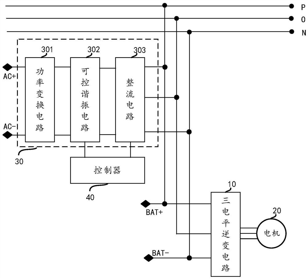
[0063] see image 3 , which is a schematic diagram of an electric drive system provided in an embodiment of the present application.

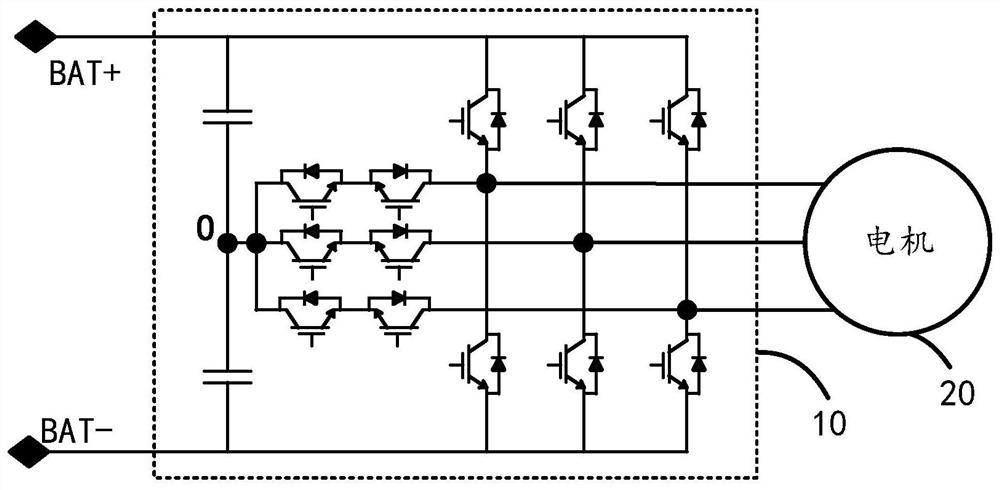
[0064] The electric drive system includes a bus bar, a three-level inverter circuit 10 , an on-board charger 30 and a controller 40 .

[0065] Wherein, the bus includes a positive bus (indicated by P in the figure) and a negative bus (indicated by N in the figure).

[0066] The on-board charger 30 includes a power conversion circuit 301 , a controllable resonance circuit 302 and a rectification circuit 303 .

[0067] The input end of the power conversion circuit 301 is the input end of the vehicle charger 30 , and the output end of the power conversion circuit 301 is connected to the...

Embodiment 2

[0088] In the embodiment of the present application, the on-board charger is used as an example for illustration.

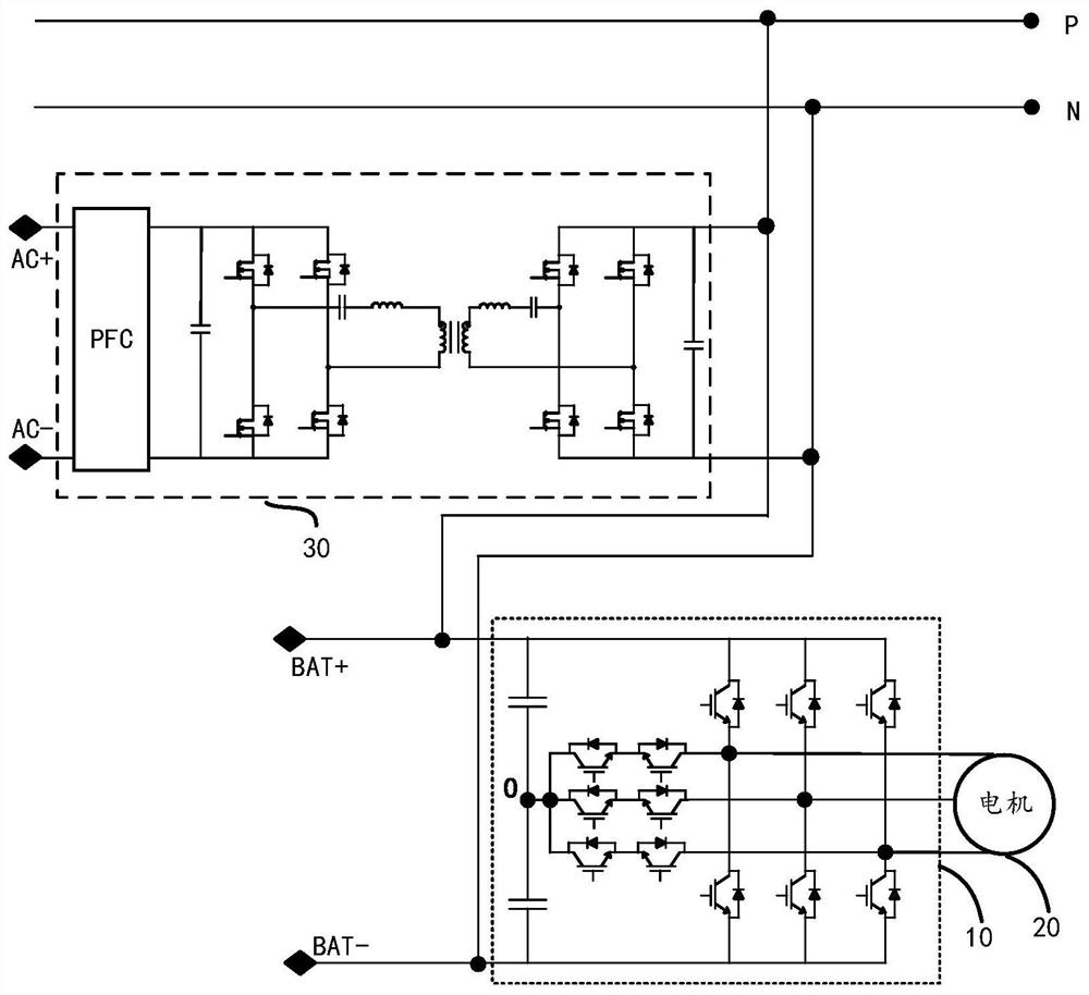
[0089] see Figure 6 , which is a schematic diagram of another electric drive system provided in the embodiment of the present application.

[0090] The vehicle charger 30 shown in the figure is a CLLC type vehicle charger, and its power conversion circuit 301 is an LLC resonant conversion circuit.

[0091] The controllable resonant circuit 302 of the on-board charger 30 includes a controllable switch S and a resonant unit. The resonant unit includes a first inductor L and a first capacitor Co connected in series.

[0092] In some other embodiments, the first inductance L may also represent the equivalent inductance of multiple inductors, and the first capacitance may also represent the equivalent capacitance of multiple capacitors.

[0093] The controllable switch S may be a controllable switch tube.

[0094] The secondary winding of the CLLC type vehicle ch...

Embodiment 3

[0116] The working principle of the electric drive will be described below in conjunction with another specific implementation manner.

[0117] see Figure 8 , which is a schematic diagram of another electric drive system provided in the embodiment of the present application.

[0118] The vehicle charger 30 shown in the figure is an LLC type vehicle charger, and its power conversion circuit 301 is an LLC resonant conversion circuit.

[0119] The controllable resonant circuit 302 of the on-board charger 30 includes a first controllable switch S1 , a second controllable unit S2 and a resonant unit. The resonant unit includes a first inductor L and a first capacitor Co connected in series.

[0120] The first controllable switch S1 and the second controllable switch S2 may be controllable switch tubes.

[0121] The first output terminal of the power conversion circuit 301 is connected to the first terminal of the first controllable switch S1 and the first input terminal of the ...


PUM


Abstract

The invention provides an electric driving system, a power assembly and an electric automobile, and relates to the technical field of electronic circuits. The electric driving system comprises a bus,a vehicle-mounted charger, a three-level inverter circuit and a controller. The bus comprises a positive bus and a negative bus and is used for connecting the input end of the three-level inverter circuit; the vehicle-mounted charger comprises a power conversion circuit, a controllable resonance circuit and a rectification circuit; and the input end of the power conversion circuit is the input endof the vehicle-mounted charger, and the output end of the power conversion circuit is connected with the rectification circuit through the controllable resonance circuit. The first output end of therectification circuit is connected with the positive bus, the second output end of the rectification circuit is connected with the negative bus, and the third output end is connected with a bus midpoint; and when the three-level inverter circuit works, the controller controls the working states of the controllable resonance circuit and the rectification circuit, so that the potential of the midpoint of the bus is balanced. By means of the electric driving system, the adjusting capacity of bus neutral point potential balance of the three-level inverter circuit is improved.

Description

technical field [0001] The present application relates to the technical field of electric power, and in particular to an electric drive system, a vehicle charger, a power assembly and an electric vehicle. Background technique [0002] With the aggravation of energy shortage and environmental pollution in modern society, electric vehicles, as new energy vehicles, have received widespread attention from all walks of life. Because the electric drive system of electric vehicles directly affects the safety and efficiency of electric vehicles, the electric drive system has always been a research hotspot. [0003] Compared with the traditional two-level electric drive system, the three-level electric drive system can effectively improve the NEDC (New European Driving Cycle) efficiency of the electric drive system, reduce the harmonic content of the output voltage and optimize the electromagnetic interference performance etc., and thus gradually become the object of research. [0...

Claims


Application Information

Patent Timeline
IPC IPC(8): H02M7/487H02M3/335H02P27/08H02M1/42B60L15/32
CPCH02M7/487H02M3/33584H02P27/085H02M1/4233H02M1/4241B60L15/32B60L2220/50Y02T10/64
Inventor 章雪亮封宁波陈跃
Owner 华为电动技术有限公司
Why Eureka
Try Eureka