A high-pressure composite gas cylinder

A gas cylinder and high-pressure technology, applied in pressure vessels, fixed-capacity gas storage tanks, gas/liquid distribution and storage, etc., can solve problems such as low production efficiency, heavy bottle weight, and carbon fiber cutting, so as to improve service life, The effect of improving the production cycle and strong structural performance

Active Publication Date: 2021-12-28
SOUTHEAST UNIV +1
View PDF10 Cites 0 Cited by
  • Summary
  • Abstract
  • Description
  • Claims
  • Application Information

AI Technical Summary

Problems solved by technology

[0003] There are the following technical defects in the structure of the existing high-pressure composite gas cylinder: (1) The bottle body structure is made of plastic material, and when it is connected with the metal sealing structure at the bottle mouth, the tightness of the two fits is relatively small. Low, when the gas cylinder is in a long-term process, the sealing structure at the bottle mouth is easily loosened due to vibration, bumping and other factors, which affects the service life of the gas cylinder
(2) The manufacturing technology of the liner in the prior art is that the head of the liner is injection-molded and then welded with the bottle body. The production efficiency of this production process is low
(3) After the inner tank is finished, the subsequent winding process is required. The mouth of the bottle is made of metal. Due to its own processing characteristics, the metal cannot achieve a close fit transition with the inner tank, which may cause the subsequent winding to be loose and have cavities. , or cause damage to the carbon fiber itself such as cutting
(3) The winding layer of the bottle body is usually made of carbon fiber material. When winding a large-volume gas cylinder, due to the length and weight of the gas cylinder, both ends of the gas cylinder need to be fixed to prevent the gas cylinder from shaking during winding. There is no structure in the prior art that can clamp and fix the bottom of the bottle
(4) The overall cylinder body weight of the existing gas cylinder structure is relatively heavy

Method used


Image

  • A high-pressure composite gas cylinder
  • A high-pressure composite gas cylinder
  • A high-pressure composite gas cylinder

Examples


Embodiment Construction

[0048] In order to make the technical solution of the present invention clearer, the present invention will be further described below in conjunction with the accompanying drawings. Any solution obtained by equivalent replacement and conventional reasoning of the technical features of the technical solution of the present invention falls within the protection scope of the present invention. The fixed connection, fixed arrangement, and fixed structure mentioned in this embodiment are known technologies known to those skilled in the art, such as gluing, welding, blow molding, screw connection, bolt-nut connection, and riveting.

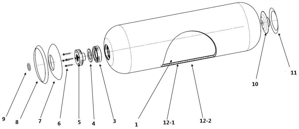
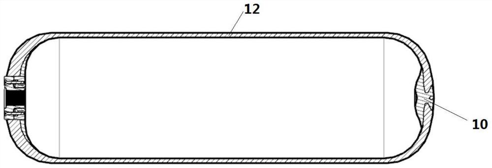
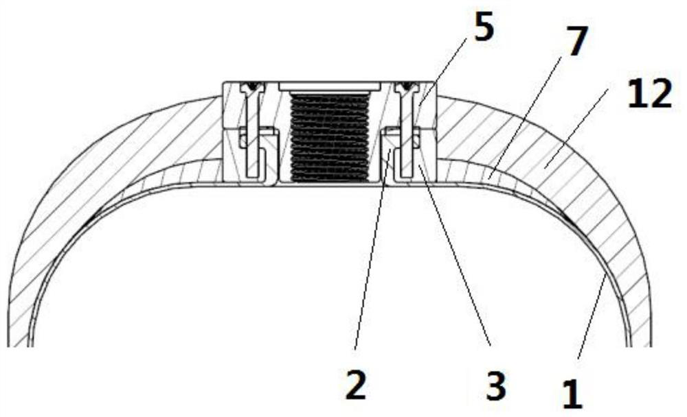
[0049] It can be seen from the accompanying drawings that a high-pressure composite gas cylinder includes an inner tank, a bottle mouth, a sealing structure, a lining, a top tape, a sealing ring, a bottom flange, a bottom tape, and a winding layer;

[0050] The section of the mouth of the bottle is in the shape of "I", the mouth of the bottle is arranged...


PUM

PropertyMeasurementUnit
elongation at breakaaaaaaaaaa

Abstract

A high-pressure composite gas cylinder, including an inner tank, a bottle mouth, an inner liner, a top tape, a sealing ring, a bottom flange, a bottom tape, and a winding layer; The liner is fixed; the lining is set at one end of the liner; the seam between the liner and the liner is fixed by wrapping the top tape; the sealing ring and the sealing structure are fixed; the bottom flange is set at the bottom of the liner; the bottom flange is connected to the inner liner The seams of the liner are wrapped and fixed by the bottom tape; the winding layer is set on the outer wall of the liner, and the winding layer is fixed to the liner by winding. The invention is designed with a sealing structure, high sealing performance, high structural strength, strong structural performance of the bottle body, and light weight of the gas cylinder.

Description

technical field [0001] The invention relates to the field of high-pressure composite gas cylinders, in particular to a high-pressure composite gas cylinder. Background technique [0002] Gas cylinders are disposable or refillable mobile pressure containers used to store and transport permanent gases, liquefied gases and dissolved gases. There are seamless gas cylinders and welded gas cylinders in terms of structure, and steel in terms of material. Gas cylinders, aluminum alloy cylinders, composite gas cylinders and other material cylinders are classified into permanent gas cylinders, liquefied gas cylinders and dissolved acetylene cylinders from the filling medium; the inner liner of the high-pressure container is made of plastic material. These products have superior properties such as corrosion resistance, fatigue resistance, and light weight, and meet the requirements of lightweight. [0003] There are the following technical defects in the structure of the existing high...

Claims


Application Information

Patent Timeline
Patent Type & Authority Patents(China)
IPC IPC(8): F17C1/08F17C1/14F17C1/16F17C13/00
CPCF17C1/08F17C1/16F17C1/14F17C13/002F17C2201/0109F17C2201/035F17C2203/011F17C2221/01F17C2223/035
Inventor 朱明泽吴伟徐春祥
Owner SOUTHEAST UNIV
Why Eureka
Try Eureka