
Television backlight film and manufacturing process thereof

A production process and backlight film technology, applied in optics, nonlinear optics, instruments, etc., can solve the problems of limited astigmatism design function, debugging visual effect, high processing cost, high defect rate, etc., to achieve comprehensive cost advantage, simple processing, Sustained low cost effect

Pending Publication Date: 2020-05-19
REGENCY OPTICS ELECTRON CORP
View PDF0 Cites 0 Cited by
  • Summary
  • Abstract
  • Description
  • Claims
  • Application Information

AI Technical Summary

Problems solved by technology

[0005] Aiming at the deficiencies of the prior art, the present invention provides a TV backlight film, which solves the short OD backlight module lamp lens design astigmatism design function in the above-mentioned background technology and has limited debugging visual effects, which may easily cause bright lights on the edge of the backlight module. The phenomenon of edge and dark edge, and the light absorption effect of black ink can effectively improve the bright edge and dark edge of the edge, so that the uniformity of the whole picture can reach more than 70%, but this process is complicated, the processing cost is high, and the defect The problem of high rate and high unit price

Method used


Image

  • Television backlight film and manufacturing process thereof
  • Television backlight film and manufacturing process thereof
  • Television backlight film and manufacturing process thereof

Examples


Embodiment Construction

[0030] The following will clearly and completely describe the technical solutions in the embodiments of the present invention with reference to the accompanying drawings in the embodiments of the present invention. Obviously, the described embodiments are only some, not all, embodiments of the present invention.

[0031] In the description of the present invention, unless otherwise stated, the meaning of "plurality" is two or more; the terms "upper", "lower", "left", "right", "inner", "outer" , "front end", "rear end", "head", "tail", etc. indicate the orientation or positional relationship based on the orientation or positional relationship shown in the drawings, and are only for the convenience of describing the present invention and simplifying the description, rather than Nothing indicating or implying that a referenced device or element must have a particular orientation, be constructed, and operate in a particular orientation should therefore not be construed as limiting ...


PUM

PropertyMeasurementUnit
diameteraaaaaaaaaa
diameteraaaaaaaaaa
diameteraaaaaaaaaa

Abstract

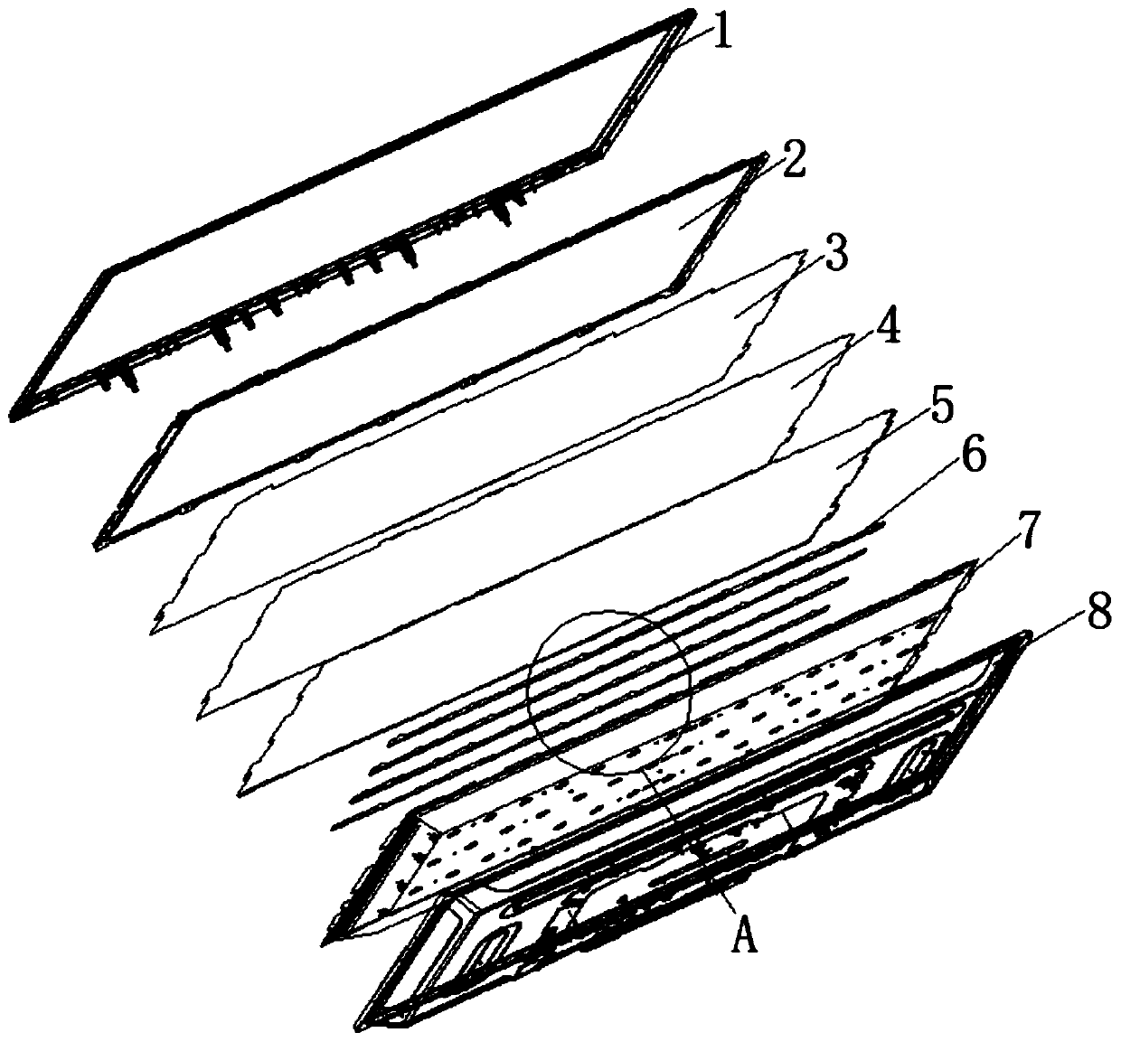
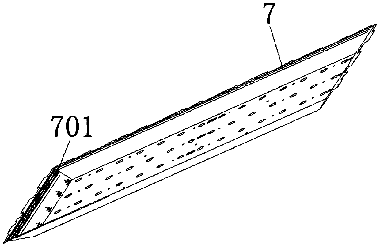
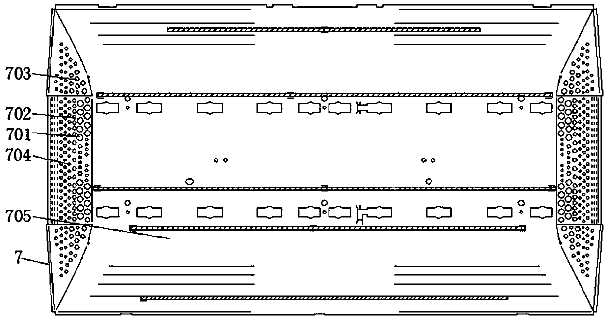
The invention discloses a television backlight film and a manufacturing process thereof. The invention relates to the technical field of television backlight films. The television backlight film comprises a substrate, the television comprises a television surface shell and a backboard, a middle frame is installed below the television face shell, a first membrane is installed below the middle frame, a second membrane is installed below the first membrane, a diffusion plate is installed below the second membrane, a light bar is installed below the diffusion plate, a reflector plate is installedbelow the light bar, and the backboard is located below the reflector plate. The invention discloses a reflector plate structure of a television backlight film. Holes are punched in the edges and broken lines are increased; the backlight module is assembled on backlight, light refraction is removed through fold line change, light is emitted out through punching, the light absorption effect is equivalent to the effect of light absorption, refraction of the edge and the light reflection amount are changed, and therefore obvious bright edges and dark edges do not appear on the edge of the backlight, and the effects that the whole picture is high in uniformity and free of dark width and bright edges are achieved.

Description

technical field [0001] The invention relates to the technical field of television backlight films, in particular to a television backlight film. Background technique [0002] If you want to live longer in the market, you must have high added value and attractive products, so that people will consume them. LCD TV is a relatively mature industry at present. If you want to take a step closer to a mature industry, There must be innovation, and innovation will inject new vitality into the enterprise. [0003] Ultra-thin direct-type LED LCD TVs are developing rapidly at present, and the beautiful appearance, ultra-thin body, and borderless design are more and more popular among consumers, and the perfect realization of this design is a great opportunity for some short OD (OD22 For the backlight module of the following), it must be mentioned here that the reflective sheet that reflects light in the backlight module plays a vital role. The purpose of the reflective sheet is to refl...

Claims


Application Information

Patent Timeline
Patent Type & Authority Applications(China)
IPC IPC(8): G02F1/13357
CPCG02F1/133606G02F1/133611
Inventor 何小磊
Owner REGENCY OPTICS ELECTRON CORP
Learn More