Oil tank of hydraulic machine

A technology of hydraulic presses and oil tanks, which is applied in the direction of presses, fuel supply tanks, mechanical equipment, etc. It can solve the problems of lack of automatic cleaning function, unsatisfactory cooling effect, and poor filtering effect, so as to speed up heat loss and novel structure , the effect of convenient filtering

Pending Publication Date: 2020-05-26
建湖奥托斯液压机械制造有限公司
View PDF9 Cites 2 Cited by
  • Summary
  • Abstract
  • Description
  • Claims
  • Application Information

AI Technical Summary

Problems solved by technology

As a general non-cut forming processing equipment, the hydraulic press uses the pressure of the liquid to transfer energy to complete various pressure processing. However, the existing hydraulic presses have the following problems: First, most of the failures of the hydraulic press are caused by hydraulic oil. It is caused by the medium mixed in the medium, so keeping the hydraulic oil clean is a necessary condition for the normal operation of the hydraulic machine, so it is necessary to set up a filter device to filter the hydraulic oil to remove the sundries in the hydraulic oil, but the filtering

Method used


Image

  • Oil tank of hydraulic machine
  • Oil tank of hydraulic machine
  • Oil tank of hydraulic machine

Examples


Embodiment Construction

[0044] The present invention will be further described below in conjunction with the accompanying drawings and specific embodiments.

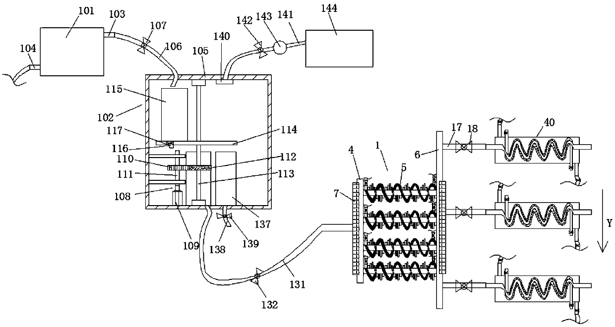
[0045] A hydraulic oil tank, comprising a tank body 101, a filtering device 102, and a cooling device 1;

[0046] The upper part of the fuel tank body 101 is provided with an oil outlet pipe 103, and one end of the oil outlet pipe 103 communicates with the fuel tank body 101, and the other end is connected with the filter device 102;

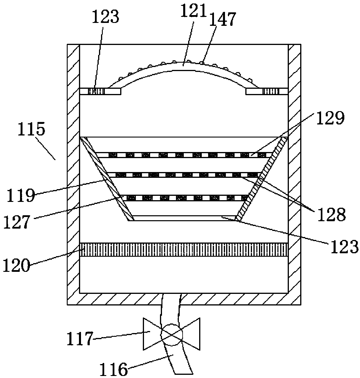
[0047] The filter device 102 includes a housing 105, a first filter cartridge 115, a second filter cartridge 130, a driving device 108, a waste water cartridge 137, a Siemens PLC controller 148, and an annular workbench 114;

[0048] An oil inlet pipe 106 is provided on the upper surface of the casing 105, one end of the oil inlet pipe 106 communicates with the casing 105, and the other end is connected with the oil outlet pipe 103; the oil inlet pipe 106 is provided with a first solenoid valve 107;

[0049] The...


PUM


Abstract

The invention provides an oil tank of a hydraulic machine. With the oil tank, a filtering device and a radiating device are used for removing impurities and cooling for hydraulic oil to ensure stableoperation of the hydraulic machine; the filtering work of the hydraulic oil in a first filtering cylinder and a second filtering cylinder is sequentially completed through a driving device, the cleaning work of the first filtering cylinder is completed, the working strength is greatly reduced, the continuity and the high efficiency of the filtering work of the first filtering cylinder are guaranteed, and the influence on the filtering effect caused by the residue of the filtering impurities is avoided; automation and intelligentization of the filtering device are realized by utilizing a PLC, liquid level sensors and electromagnetic valves, so that cleaning and filtering are more convenient; a main branch pipe plays a shunting role, so that the hydraulic oil is preliminarily cooled in a first radiating pipe, and the heat loss of the hydraulic oil in the first radiating pipe is accelerated by combining water cooling with air cooling; and the hydraulic oil is secondarily cooled through cooling devices, the cooling time of the hydraulic oil in inner pipes is prolonged by utilizing inner and outer spiral structures of a second radiating pipe, and the cooling reliability is greatly improved.

Description

technical field [0001] The invention relates to the technical field of hydraulic equipment, in particular to a hydraulic oil tank. Background technique [0002] Hydraulic press is one of the most widely used equipment in product forming production, and has become one of the indispensable equipment in industrial production. Due to the wide adaptability of the hydraulic press in the work, it has been widely used in various sectors of the national economy. Such as plate forming; pipe, wire, profile extrusion; powder metallurgy, plastic and rubber product forming; plywood pressing and packaging; artificial diamond, refractory brick pressing and carbon electrode pressing forming; The rapid development of various types of hydraulic presses has effectively promoted the development and progress of various industries. As a general non-cut forming processing equipment, the hydraulic press uses the pressure of the liquid to transfer energy to complete various pressure processing. How...

Claims


Application Information

Patent Timeline
IPC IPC(8): F15B1/26F15B21/041F15B21/0423B30B15/00
CPCF15B1/26F15B21/041F15B21/042B30B15/00
Inventor 李勇祥
Owner 建湖奥托斯液压机械制造有限公司
Why Eureka
Try Eureka