Gas-phase reaction buffer chamber based on atmospheric pressure microwave plasma torch

A technology of microwave plasma and gas buffer chamber, which is applied in the field of plasma technology and environmental chemistry application, to achieve the effect of increasing chemical reaction rate, increasing plasma density and electron temperature

Pending Publication Date: 2020-05-29
李容毅
View PDF11 Cites 9 Cited by
  • Summary
  • Abstract
  • Description
  • Claims
  • Application Information

AI Technical Summary

Problems solved by technology

[0005] The present invention proposes a solution to improve the performance of the existing atmospheric pressure microwave plasma tor...

Method used


Image

  • Gas-phase reaction buffer chamber based on atmospheric pressure microwave plasma torch
  • Gas-phase reaction buffer chamber based on atmospheric pressure microwave plasma torch
  • Gas-phase reaction buffer chamber based on atmospheric pressure microwave plasma torch

Examples


Embodiment 1

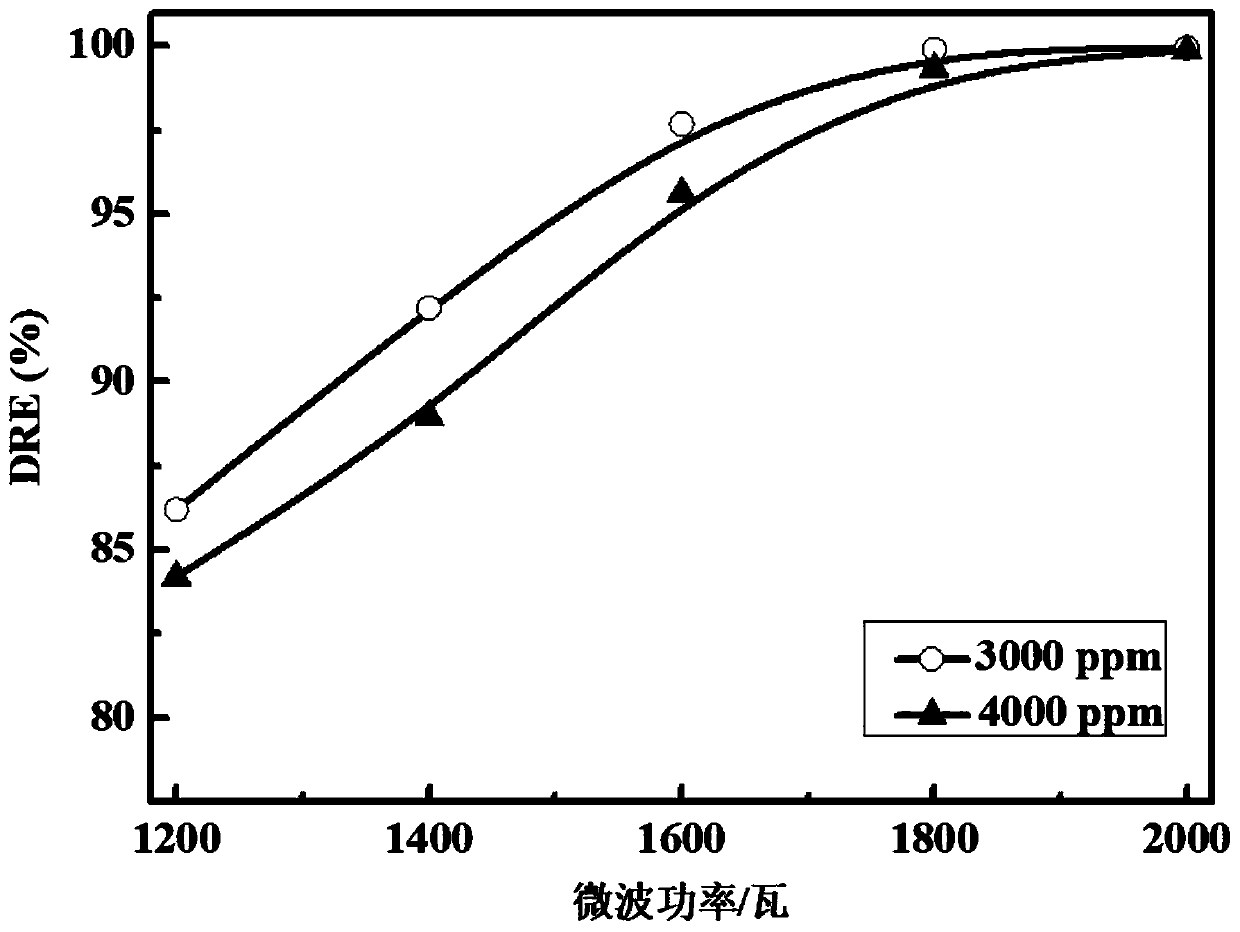
[0039] CF 4 Degradation experimental results. Under the condition of nitrogen as the background gas, turn on the microwave plasma torch, set the gas flow rate to 15 L / min and the microwave power to 1000W, so that the plasma discharge remains stable, and CF is mixed into the plasma carrier gas 4 Gas, the concentration of gas gradually increases from the minimum value to the set value to keep the discharge stable. Measurements are obtained at CF 4 The ratio of mixed nitrogen carrier gas is 3000ppm and 4000ppm respectively, and the total gas flow rate is 15 liters per minute. The degradation rate DRE value changes with the microwave power. The definition method of DRE is as follows:

[0040]

[0041] where C before and Cafter Represent the CF before and after plasma removal obtained from the FTIR spectra, respectively 4 concentration. figure 1 Shown is CF 4 When the concentration is 3000ppm and 4000ppm respectively, the application patent CN207070436U proposes a kind of...

Embodiment 2

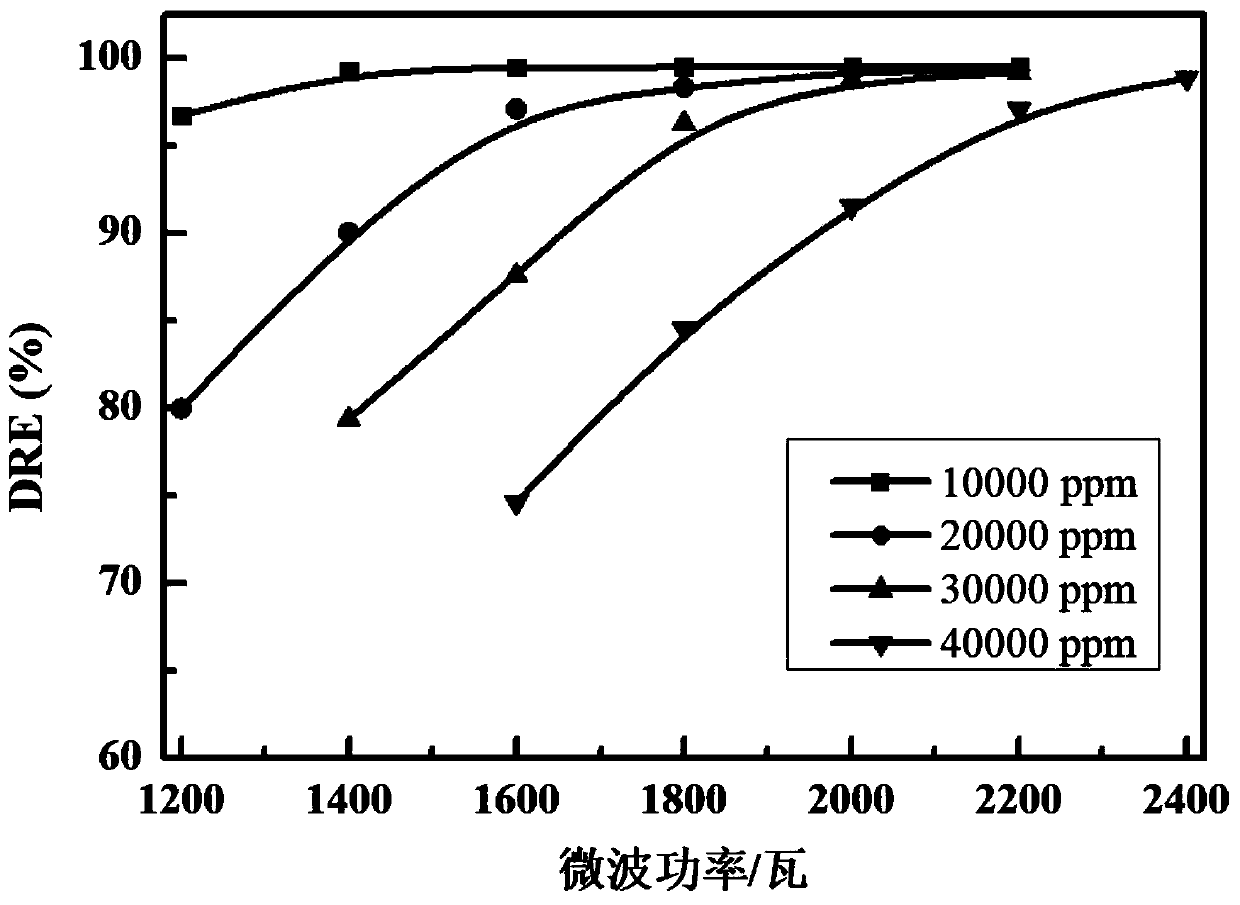
[0043] Application of patent CN207070436U proposed a dual-chamber excited atmospheric pressure microwave plasma torch and the gas phase reaction buffer chamber of the present invention for SF 6 Degradation experimental data. Under the condition of nitrogen as the background gas, turn on the microwave plasma torch, gradually switch from nitrogen to oxygen under the condition of keeping the total flow rate of 15 liters / min, and finally discharge under the condition of pure oxygen carrier gas. Set the gas flow rate to 15 L / min and the microwave power to 1000W to keep the plasma discharge stable, and mix SF into the plasma carrier gas 6 Gas, the gas concentration gradually increases from the small to the set value to keep the discharge stable. Measurements got in SF 6 The ratio of mixed oxygen carrier gas is 10000ppm, 20000ppm, 30000ppm, and 4000ppm respectively, under the condition that the total gas flow rate is 15 liters per minute, the degradation rate DRE value changes with...


PUM


Abstract

The invention discloses a gas-phase reaction buffer chamber based on an atmospheric pressure microwave plasma torch, and belongs to the field of plasma technology and environmental chemistry application. The gas-phase reaction buffer chamber comprises a gas injection part, a buffer chamber, a gas-pressure meter and an exhaust pump; the buffer chamber is arranged above the gas injection part, and the top of the buffer chamber is connected with the gas-pressure meter and the exhaust pump; the gas injection part comprises a rectangular waveguide, a movable metal baffle, a buffer chamber flange and a discharge tube, working gas is introduced into the discharge tube to form a vortex gas flow field, and the working gas in the discharge tube is induced by a microwave electric field to be ionizedto form microwave plasma discharge. Certain working air pressure is kept in the buffer chamber, so that the plasma torch is kept in a stable discharge state. According to the invention, the plasma density and the electron temperature in the interaction area of the plasma and the gas can be increased, the chemical reaction rate of the plasma gas-phase reaction can be further improved, and the gas introduced into the discharge tube can completely and fully participate in the plasma chemical reaction.

Description

technical field [0001] The invention relates to an invention of a gas phase reaction buffer chamber based on an atmospheric pressure microwave plasma torch, which belongs to the application field of plasma technology and environmental chemistry. Background technique [0002] The gas temperature of the electrodeless contamination plasma produced by the atmospheric pressure microwave plasma torch is usually in the range of 3000-6000K, and the electron density is 10 14 cm -3 Above, the resulting highly active plasma atmosphere is very suitable for chemical gas phase reactions, and the high energy density also ensures a large gas flux (>100m 3 / h) The plasma can maintain a stable discharge state. In addition, considering the high energy utilization rate of microwave plasma (up to 60%) and the advantages of working under normal pressure without the need for a vacuum system, from the perspective of application effectiveness and economy, not only in terms of gas modification, ...

Claims


Application Information

Patent Timeline
IPC IPC(8): B01J19/12
CPCB01J19/126
Inventor 李容毅韩涤非陈芳赵纪军周思
Owner 李容毅
Why Eureka
Try Eureka