A composite material workpiece surface cleaning system and method
A workpiece surface, cleaning system technology, applied in cleaning methods and utensils, cleaning methods using gas flow, chemical instruments and methods, etc. Cleaning and other issues to achieve the effect of preventing failure, prolonging continuous working time, and efficient cooling effect
- Summary
- Abstract
- Description
- Claims
- Application Information
AI Technical Summary
Problems solved by technology
Method used
Image
Examples
Embodiment 1
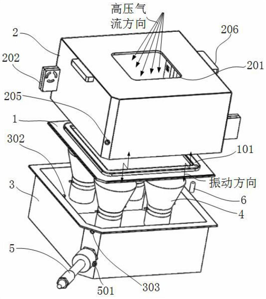
[0049] This embodiment discloses a composite material workpiece surface cleaning system, which includes an ultrasonic vibration device, a temperature control module, a cooling module, a control module and a high-pressure air jet device.
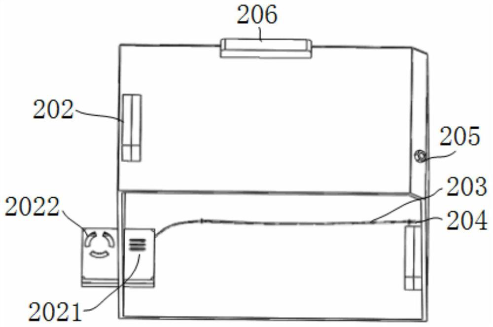
[0050] see figure 1 , the ultrasonic vibration device includes a loading platform 1 , an upper cover 2 , a box body 3 and an ultrasonic transducer 4 .
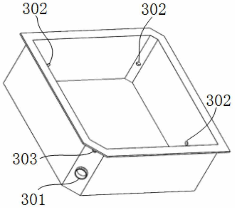
[0051] see image 3 , the lower end of the box body 3 is closed, and the upper end is open. The lower end of the box body 3 is fixed on a horizontal plane. The side wall of the box body 3 has a cooling gas inlet 301 and three heat exchange gas outlets 302 . The outlet area of the heat exchange gas outlet 302 is denoted as S 1 , denote the inlet area of the cooling gas inlet 301 as S 2 , S 2 / 61 2 / 3. The terminal II303 is also fixed on the side wall of the box body 3 .
[0052] There are four ultrasonic transducers 4, and the four ultrasonic transducers 4 are horizontally fixed in...
Embodiment 2
[0070] This embodiment provides a relatively basic implementation method, a composite material workpiece surface cleaning system, including an ultrasonic vibration device, a temperature control module, a cooling module, a control module and a high-pressure air jet device.
[0071] see figure 1 , the ultrasonic vibration device includes a loading platform 1 , an upper cover 2 , a box body 3 and an ultrasonic transducer 4 .
[0072] see image 3 , the lower end of the box body 3 is closed, and the upper end is open. The lower end of the box body 3 is fixed on a horizontal plane. The side wall of the box body 3 has a cooling gas inlet 301 and three heat exchange gas outlets 302 . The outlet area of the heat exchange gas outlet 302 is denoted as S 1 , denote the inlet area of the cooling gas inlet 301 as S 2 , S 2 / 61 2 / 3. The terminal II303 is also fixed on the side wall of the box body 3 .
[0073] There are four ultrasonic transducers 4, and the four ultrasonic tra...
Embodiment 3
[0087] The main structure of this embodiment is the same as that of Embodiment 2. Further, the lower end of the loading platform 1 is welded with a short external threaded rod, and the ultrasonic transducer 4 has an internal thread, and the loading platform 1 is connected to the ultrasonic transducer by a thread. On the device 4, the contact surface between the ultrasonic transducer 4 and the object-carrying platform 1 is coated with an adhesive, so that the ultrasonic transducer 4 and the object-carrying platform 1 are closely connected to ensure uniform ultrasonic transmission process.
PUM
 Abstract
Description
Claims
Application Information
 - R&D
- Intellectual Property
- Life Sciences
- Materials
- Tech Scout
- Unparalleled Data Quality
- Higher Quality Content
- 60% Fewer Hallucinations
Browse by: Latest US Patents, China's latest patents, Technical Efficacy Thesaurus, Application Domain, Technology Topic, Popular Technical Reports.
© 2025 PatSnap. All rights reserved.Legal|Privacy policy|Modern Slavery Act Transparency Statement|Sitemap|About US| Contact US: help@patsnap.com


