
Ship crankshaft polisher

A polishing machine and crankshaft technology, applied in the mechanical field, can solve the problems of no quality assurance, low polishing efficiency, laborious polishing methods, etc., and achieve the effect of good centering effect and simple structure

Pending Publication Date: 2020-05-29
LIAONING 518 INTERNAL COMBUSTION ENGINE FITTINGS
View PDF0 Cites 1 Cited by
  • Summary
  • Abstract
  • Description
  • Claims
  • Application Information

AI Technical Summary

Problems solved by technology

For marine crankshafts with an axial dimension greater than 2m, there is no special polishing machine. The existing treatment method is to directly use sandpaper to manually polish the journal. The polishing quality depends entirely on the operator's experience during the polishing operation. Such polishing The method is laborious, the polishing efficiency is not high, and there is no quality assurance

Method used


Image

  • Ship crankshaft polisher
  • Ship crankshaft polisher
  • Ship crankshaft polisher

Examples


Embodiment Construction

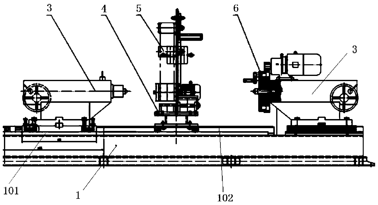
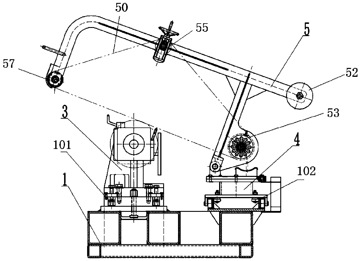
[0031] The present invention will be described in detail below in conjunction with the accompanying drawings. As shown in the figure, the present invention includes a bed 1 on which a first guide rail 101 and a second guide rail 102 are arranged, and the first guide rail and the second guide rail are parallel; one end on the first guide rail is arranged Tailstock moving plate 31, tailstock 3 is fixedly set on the tailstock moving plate, driving device 6 is fixedly set above the fixed tailstock at the other end; mobile platform 4 is set on the second guide rail, and polishing arm 5 is set on the moving platform; Both the tailstock moving plate 31 and the moving platform 4 are provided with stabilizing devices;

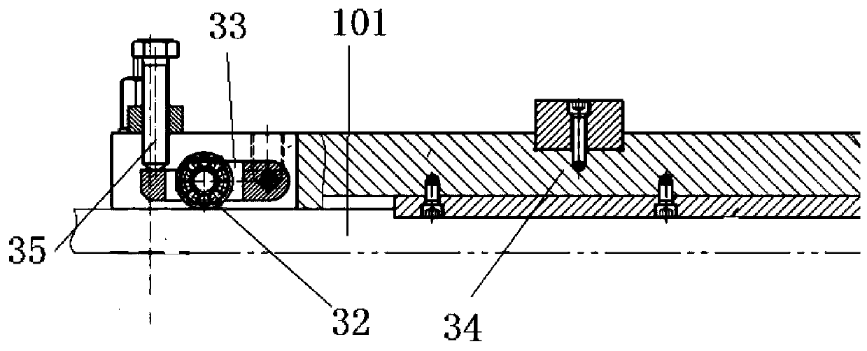
[0032] The tailstock moving plate 34 is provided with a stroke adjustment device, and the stroke adjustment device includes a plurality of sets of bearings 32 rolling on the first track, the bearings are fixed on the bearing support plate 33, and one end of the bearing s...


PUM


Abstract

The invention discloses a ship crankshaft polisher. The ship crankshaft polisher comprises a lathe body; the lathe body is provided with a first guide rail and a second guide rail; the first guide rail and the second guide rail are parallel to each other; one end of the first guide rail is provided with a tail seat moving plate; the tail seat moving plate is fixedly provided with a tail seat; theother end of the first guide rail is provided with a fixed tail seat; a driving device is fixedly arranged at the upper portion of the fixed tail seat; the second guide rail is provided with a movingplatform; and the moving platform is provided with a polishing arm. The ship crankshaft polisher disclosed by the invention has the advantages that (1) the ship crankshaft polisher can adapt to crankshafts different in length by virtue of adjustment of the tail seat, and a radial adjusting structure of the moving platform also adapts to the adjustment of the crankshafts different in diameter; (2)integration of the tail seat and the driving device is adopted, a pull rod is used for driving the crankshaft to rotate, and the end part of the crankshaft is not provided with a driving device whichis relatively large in size, so the structure is simple, and a better centering effect is realized; and (3) a stroke adjusting device is used for guaranteeing up-down movement of a bearing positionedbelow the tail seat moving plate, and thus the crankshaft can be conveyed by virtue of the tail seat moving plate.

Description

technical field [0001] The invention relates to the mechanical field, in particular to a polishing machine, more specifically to a crankshaft polishing machine. Background technique [0002] The marine crankshaft is the main rotating part in the marine engine. After the connecting rod is installed, it can undertake the up and down (reciprocating) motion of the connecting rod and turn it into a cyclic (rotating) motion. There is a high-load relative rotation between the bearing bush of the connecting rod and the crankshaft journal. In addition to the high surface roughness requirements for the crankshaft journal surface, there are also high requirements for shape and position tolerances. There are chatter marks on the surface of the crankshaft journal after grinding, which cannot meet the required shape and position tolerance requirements. Polishing must be used to remove the chatter marks in order to meet the shape and position tolerance requirements of the crankshaft. [0...

Claims


Application Information

Patent Timeline
Patent Type & Authority Applications(China)
IPC IPC(8): B24B21/02B24B21/18B24B21/20
CPCB24B21/02B24B21/18B24B21/20
Inventor 张万鹏顾梦楠曲贵龙杨秀成王毅刘光宇贾闯
Owner LIAONING 518 INTERNAL COMBUSTION ENGINE FITTINGS
Learn More