Pulp dryer

A technology of a dryer and a driving mechanism, applied in the field of dryers, can solve the problems of wasting heat dissipation energy of the casing, difficult to grasp raw materials, and have a large impact on energy consumption, and achieves recovery of dehumidification capacity, increased air flow speed, and accelerated evaporation speed. Effect

Pending Publication Date: 2020-05-29
刘超山
View PDF0 Cites 1 Cited by
  • Summary
  • Abstract
  • Description
  • Claims
  • Application Information

AI Technical Summary

Problems solved by technology

At present, the main problems of the dryer are the large waste of energy for heat dissipation of the exhaust gas and the heat dissipation of the casing, the fluctuation of steam pressure has a great impact on energy consumption, the difficulty of controlling the drying of materials, and the burning of raw materials.

Method used


Image

  • Pulp dryer
  • Pulp dryer
  • Pulp dryer

Examples


Embodiment Construction

[0025] The present invention will be further described below in conjunction with drawings and embodiments.

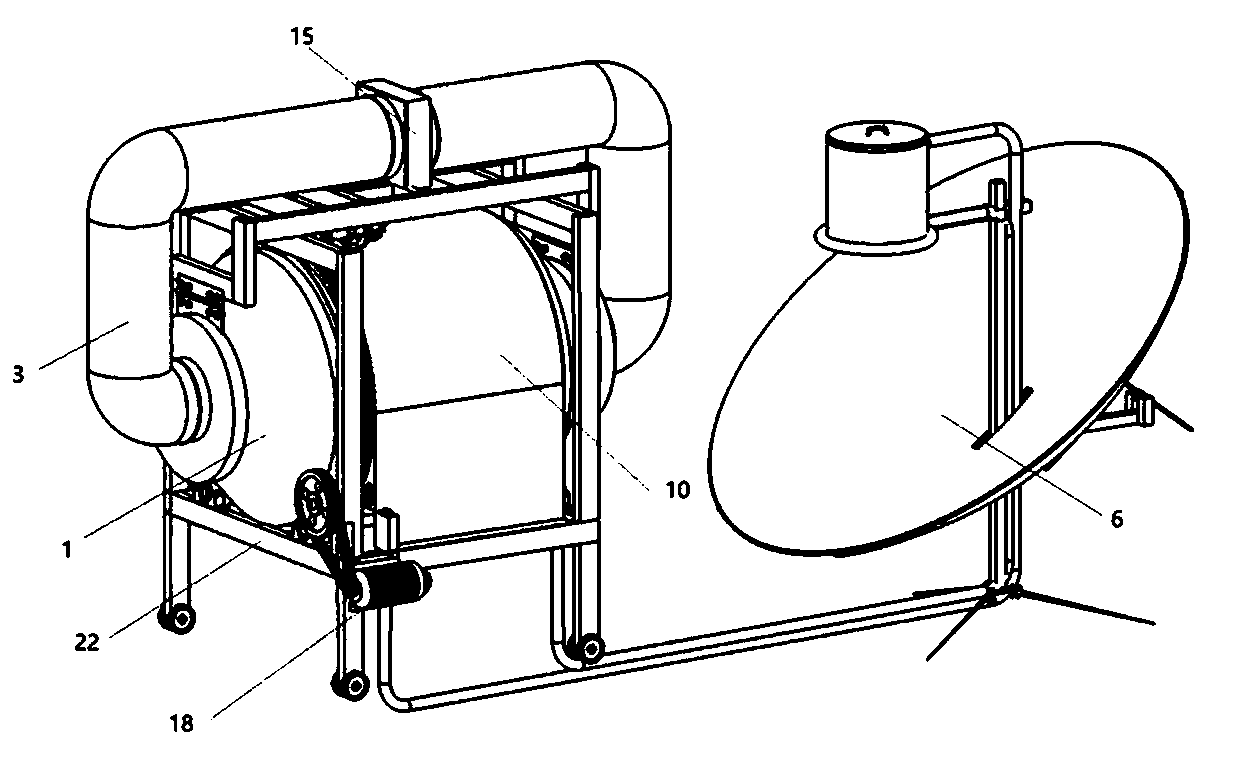
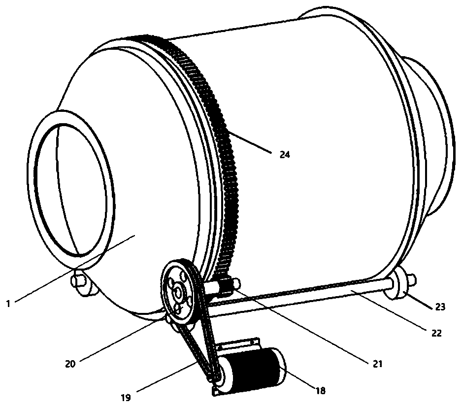
[0026] Such as Figure 1-Figure 5 Horizontal dryer shown, including drum assembly, circulating air supply assembly, heating assembly and dehumidification assembly,

[0027] The drum assembly includes a driving mechanism and a horizontal drum 1, and the driving mechanism drives and connects the horizontal drum 1;

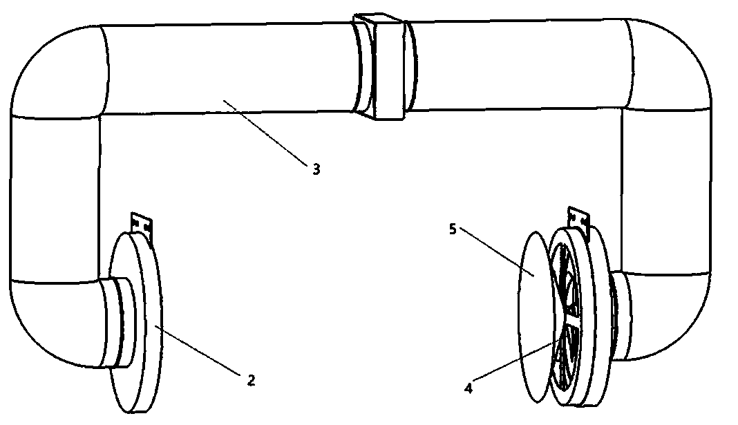
[0028] The circulating air supply assembly includes a drum cover 2, an air duct 3, a blower fan 4 and an air guide disc 5. The drum cover 2 covers the air outlet of the horizontal drum 1. The drum cover 2 is connected to the blower fan 4 through the air duct 3, and the air guide disc 5 is installed at the air outlet position of the blowing fan 4;

[0029] The heating assembly includes a solar panel 6, a solar heating tube 7, a heating power supply, a resistance wire heating tube 8, thermal insulation cotton 9 and a fixed cover 10, the solar panel 6 is connec...


PUM


Abstract

The invention discloses a horizontal dryer. The horizontal dryer comprises a roller assembly, a circulating air supply assembly, a heating assembly and a dehumidifying assembly. The horizontal dryer can achieve the effects of improving the drying speed of equipment, reducing the energy loss and reducing the energy requirement, and has certain guiding significance for enriching the types of dryersand improving the quality of the dryers.

Description

technical field [0001] The patent of the present invention relates to the technical field of dryers, in particular to a horizontal dryer. Background technique [0002] The dryer is a device that fully contacts the material with hot air, and evaporates the water in the material through heat conduction, convection, and heat radiation. Dryers can be divided into two types: industrial and civil. Industrial dryers are also called dryers. Civilian dryers are generally used to remove water from various production and living materials. The dryer is generally composed of a drum, a feeding device, a discharging device, an air induction device, an exhaust pipe, a transmission device and an electric control device. [0003] The salient features of the dryer equipment industry and the role of technical content have become increasingly prominent. The drying equipment manufacturing industry adjusts its industrial structure in accordance with the requirements of high quality, low energy c...

Claims


Application Information

Patent Timeline
Patent Type & Authority Applications(China)
IPC IPC(8): F26B11/04F26B21/00F26B21/04F26B21/08F26B23/06F26B23/10F26B25/12F26B25/16F24S20/40A23N12/08
CPCA23N12/083F24S20/40F26B11/044F26B21/004F26B21/04F26B21/083F26B23/06F26B23/10F26B25/12F26B25/16Y02E10/40
Inventor 王辉刘超山李向阳刘学凯罗庆
Owner 刘超山
Why Eureka
Try Eureka