A self-adjusting smart home security camera

A camera, self-adjusting technology, applied in image communication, cleaning methods, utensils, instruments, etc., can solve the problem that the shading effect cannot be adjusted according to the light intensity

Active Publication Date: 2021-06-01
安徽先启电子科技有限公司
View PDF6 Cites 0 Cited by
  • Summary
  • Abstract
  • Description
  • Claims
  • Application Information

AI Technical Summary

Problems solved by technology

[0005] The purpose of the present invention is to solve the problem that the shading effect cannot be adjusted according to the light intensity, and to provide a self-adjusting smart home security camera that can automatically adjust the shading effect according to the light intensity

Method used


Image

  • A self-adjusting smart home security camera
  • A self-adjusting smart home security camera
  • A self-adjusting smart home security camera

Examples


Embodiment 1

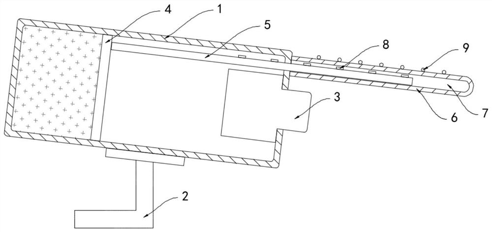
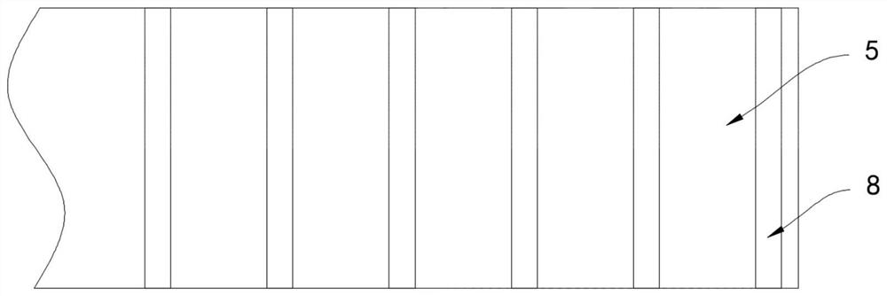
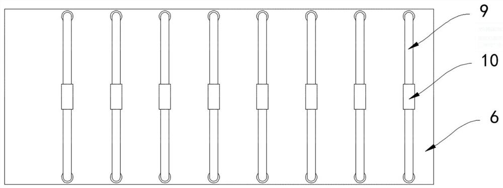
[0020] Such as Figure 1-3 As shown, a self-adjusting smart home security camera includes a housing 1 and a bracket 2 fixedly connected to the bottom of the housing 1. A camera 3 is arranged in front of the housing 1. The housing 1 is made of a light-transmitting material. The body 1 is sealed and slidably connected with a push plate 4, and the airtight space formed by the push plate 4 and the housing 1 is filled with silver bromide powder, and the side wall of the push plate 4 is fixedly connected with a light shield 5. The protective plate 6, the protective plate 6 is a transparent glass plate, the protective plate 6 is provided with a sliding cavity 7 communicating with the inside of the housing 1, the other end of the light shield 5 extends into the sliding cavity 7 and slides with the side wall of the sliding cavity 7 Connect, the upper surface of the visor 5 is equidistantly arranged with a plurality of permanent magnetic strips 8, the upper surface of the protective pla...

Embodiment 2

[0024] Such as Figure 4 As shown, the difference between this embodiment and Embodiment 1 is that a threaded rod 11 is rotatably connected to the inner wall of the housing 1, the threaded rod 11 runs through the push plate 4 and is threadedly connected with the push plate 4, and the threaded rod 11 is externally fixed A fan 12 is sleeved, and a cooling hole 13 is opened on the side wall of the casing 1 .

[0025] In this embodiment, when the air pressure pushes the push plate 4 to move, it drives the threaded rod 11 threadedly connected with it to rotate, and then drives the fan 12 to rotate, so as to speed up the airflow velocity at the cooling hole 13, thereby promoting the communication between the inside of the housing 1 and the outside world. The heat exchange has played a good fan heating effect.


PUM


Abstract

The invention belongs to the field of security monitoring, and in particular relates to a self-adjusting smart home security camera, comprising a housing and a bracket fixedly connected to the bottom of the housing, a camera is arranged in front of the housing, and the housing is composed of a material, a push plate is sealed and slidably connected in the housing, silver bromide powder is filled in the airtight space formed by the push plate and the housing, and a light-shielding plate is fixedly connected to the side wall of the push plate. A protective plate is provided above the camera, and the protective plate is a transparent glass plate. A sliding cavity communicating with the inside of the housing is provided in the protective plate. The other end of the light shielding plate extends into the sliding cavity and is connected to the sliding cavity. The side walls are slidably connected, and a plurality of permanent magnetic strips are equidistantly arranged on the upper surface of the shading plate. The invention can automatically adjust the protruding length of the shading plate according to the intensity of external light, realize the adjustment of the shading effect of the camera, and prevent the camera from being unable to take a clear picture due to light problems.

Description

technical field [0001] The invention belongs to the field of security monitoring, in particular to a self-adjusting smart home security camera. Background technique [0002] With the development of security monitoring technology, more and more families will install security cameras outside the door. For the current outdoor security cameras, they generally face the problem of strong backlight, that is, when the direction the lens is facing has a strong When the background is illuminated, such as when the camera is facing the sun, the brightness of the image captured by it is extremely low, and the image processing module can only increase the brightness of the captured image as a whole. . [0003] For this reason, a sun visor is generally installed above the lens of outdoor security cameras at present. The structural position of the sun visor is fixed, but the intensity of sunlight is not the same. As a result, when the light is strong, the shading effect of the sun visor is...

Claims


Application Information

Patent Timeline
Patent Type & Authority Patents(China)
IPC IPC(8): H04N5/225G03B17/55B08B7/02G03B11/04
CPCG03B17/55B08B7/02H04N23/50H04N23/51
Inventor 李媛孙瑜格
Owner 安徽先启电子科技有限公司
Why Eureka
Try Eureka