Check patentability & draft patents in minutes with Patsnap Eureka AI!

A method of manufacturing microfluidic actuator

A manufacturing method and actuator technology, applied to chemical instruments and methods, application of thermal effects to detect fluid flow, separation methods, etc., capable of solving insufficient compression ratio of actuating fluid, small displacement of thin film piezoelectric layer, small transmission flow rate, etc. question

Active Publication Date: 2020-06-02
MICROJET TECH
View PDF6 Cites 0 Cited by
  • Summary
  • Abstract
  • Description
  • Claims
  • Application Information

AI Technical Summary

Problems solved by technology

[0004] In the prior art, although there is an integrally formed miniaturized fluid delivery structure using micro-electromechanical processes, the existing miniaturized fluid delivery structure often suffers from the disadvantage of too small displacement of the thin-film piezoelectric layer. The problem of insufficient dynamic fluid compression ratio makes the transmission flow too small. Therefore, how to break through its technical bottleneck with innovative miniaturized structure is an important content of development.

Method used


Image

  • A method of manufacturing microfluidic actuator
  • A method of manufacturing microfluidic actuator
  • A method of manufacturing microfluidic actuator

Examples


Embodiment Construction

[0050] Some typical embodiments embodying the features and advantages of the present application will be described in detail in the description in the following paragraphs. It should be understood that the present case can have various changes in different aspects without departing from the scope of the present case, and the descriptions and diagrams therein are used for illustration in nature rather than limiting the present case.

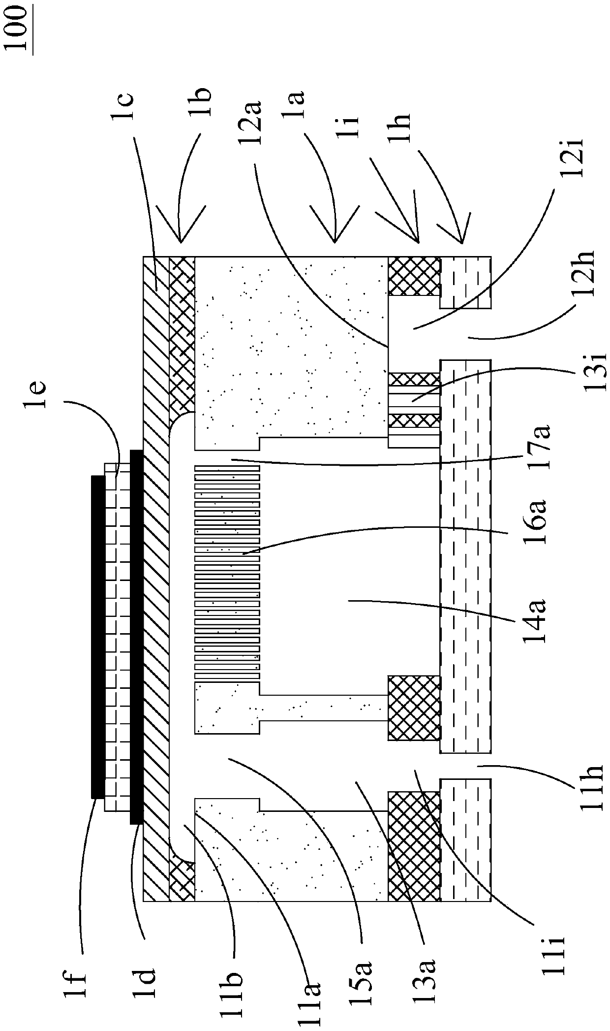
[0051] The microfluidic actuators in this case are used to transport fluids, see figure 1 , in the embodiment of this case, the microfluidic actuator 100 includes: a substrate 1a, a cavity layer 1b, a vibration layer 1c, a lower electrode layer 1d, a piezoelectric actuation layer 1e, an upper electrode layer 1f, An orifice plate layer 1h and a channel layer 1i, and their manufacturing methods are described in the following steps.

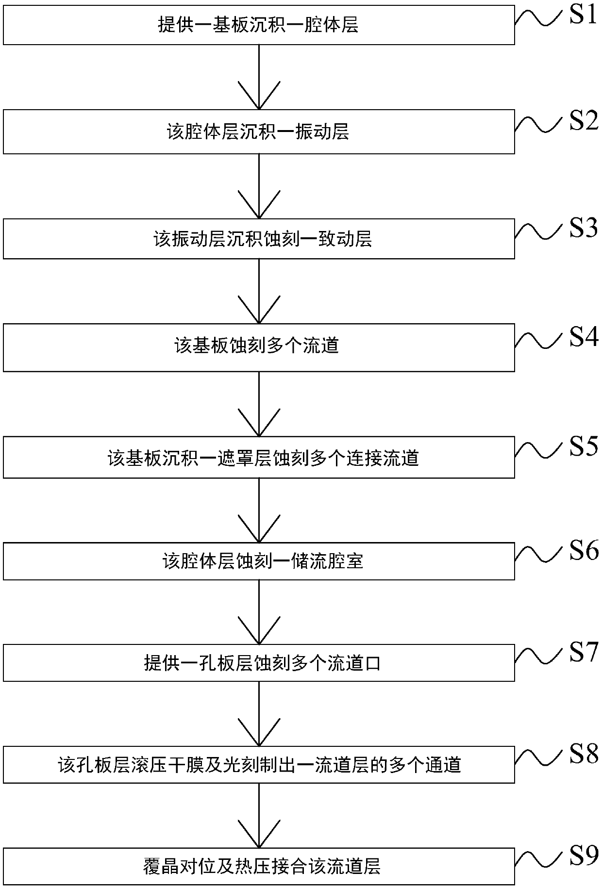
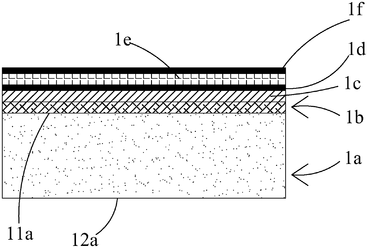
[0052] see figure 2 and Figure 3A , as shown in step S1, a substrate is provided to deposit a cavity layer, and ...


PUM

PropertyMeasurementUnit
thicknessaaaaaaaaaa

Abstract

The invention relates to a method of manufacturing microfluidic actuator, which comprises the following steps of: 1, providing a substrate, and depositing an oxidation material on the substrate to form a cavity layer; 2, depositing a nitriding material on the cavity layer to form a vibration layer; 3, depositing a metal material and a piezoelectric material on the vibration layer, and etching to form an actuating layer; 4, etching the substrate to form a plurality of flow channels; 5, depositing an oxidation material on the substrate to form a mask layer, and etching the substrate to form a plurality of connecting flow channels; 6, etching the cavity layer to form a flow storage chamber; 7, providing a pore plate layer, and etching to form a plurality of runner openings; 8, manufacturing aflow channel layer and a plurality of channels on the pore plate layer by rolling the dry film and photoetching; 9, bonding the substrate and the flow channel layer by flip chip alignment and hot pressing to form the integral structure of the microfluidic actuator.

Description

technical field [0001] This case relates to a method for manufacturing a microfluidic actuator, especially a method for manufacturing a microfluidic actuator using a microelectromechanical semiconductor process. Background technique [0002] At present, in various fields, whether it is medicine, computer technology, printing, energy and other industries, products are developing towards refinement and miniaturization. Among them, the fluid delivery included in products such as micro pumps, sprayers, inkjet heads, and industrial printing devices Structure is its key technology. [0003] With the rapid development of science and technology, the application of fluid conveying structure is becoming more and more diversified, such as industrial application, biomedical application, medical care, electronic heat dissipation, etc., and even the recent popular wearable devices can be seen. It can be seen that The traditional fluid delivery structure has gradually tended to miniaturiz...

Claims


Application Information

Patent Timeline
Patent Type & Authority Applications(China)
IPC IPC(8): B81B3/00B81B1/00B81C1/00F04B43/04
CPCB81B3/0021B81B1/002B81C1/00119B81C1/00349B81C1/00523F04B43/046B81B2201/036B81B2201/037B81B2201/05
Inventor 莫皓然余荣侯张正明戴贤忠廖文雄黄启峰韩永隆李伟铭
Owner MICROJET TECH
Features
  • R&D
  • Intellectual Property
  • Life Sciences
  • Materials
  • Tech Scout
  • Unparalleled Data Quality
  • Higher Quality Content
  • 60% Fewer Hallucinations
Learn More