
Reaction-controllable photocatalytic fiber sewage treatment equipment and use method thereof

A kind of sewage treatment equipment, photocatalysis technology, applied in water/sewage treatment equipment, light water/sewage treatment, water/sewage treatment, etc., can solve the problems of precise control of difficult-to-contact areas, difficult-to-contact areas, difficult to recycle, etc. Achieve the effects of low stirring dependence, enhanced suspension and easy recovery

Inactive Publication Date: 2020-06-02
FOSHAN JINJINGCHUANG ENVIRONMENTAL PROTECTION TECH CO LTD
View PDF0 Cites 0 Cited by
  • Summary
  • Abstract
  • Description
  • Claims
  • Application Information

AI Technical Summary

Problems solved by technology

[0005] The control of the catalytic reaction includes the control of the contact area between the catalyst and the reactant. The current conventional practice is to control the contact area of ​​the two by controlling the dosage form and dosage of the catalyst, but this method is difficult to control the contact area between the two in actual operation. The area should be controlled more precisely, especially for widely used granular catalysts. Although catalysts with different particle sizes have theoretical surface areas, due to manufacturing errors, interparticle abrasion or aggregation during transportation and storage, the actual use of It is difficult to accurately confirm the contact area between it and the reactant, and its small particle size is difficult to recover, which is likely to cause additional pollution

Method used


Image

  • Reaction-controllable photocatalytic fiber sewage treatment equipment and use method thereof
  • Reaction-controllable photocatalytic fiber sewage treatment equipment and use method thereof
  • Reaction-controllable photocatalytic fiber sewage treatment equipment and use method thereof

Examples


Embodiment Construction

[0043] The following will clearly and completely describe the technical solutions in the embodiments of the present invention with reference to the accompanying drawings in the embodiments of the present invention. Obviously, the described embodiments are only some, not all, embodiments of the present invention. Based on the embodiments of the present invention, all other embodiments obtained by persons of ordinary skill in the art without making creative efforts belong to the protection scope of the present invention.

[0044] In the following description, many specific details are set forth in order to fully understand the present invention, but the present invention can also be implemented in other ways different from those described here, therefore, the protection scope of the present invention is not limited by the specific implementation disclosed below. Example limitations.

[0045] In describing the present invention, it should be understood that the terms "center", "l...


PUM


Abstract

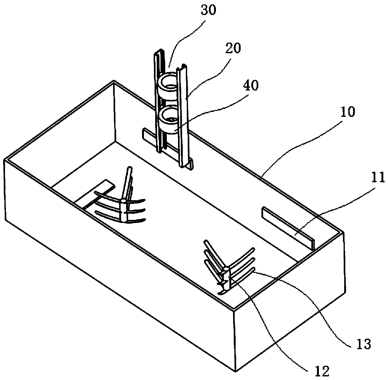
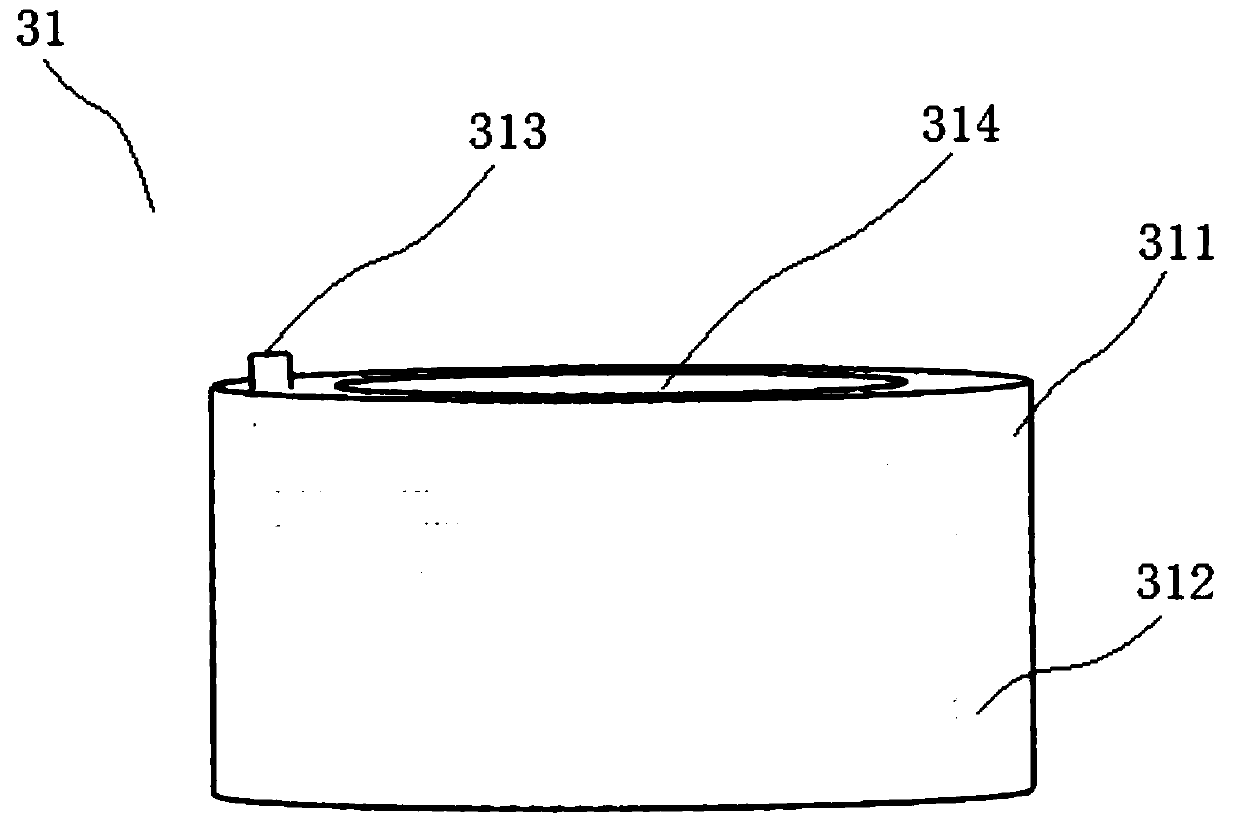
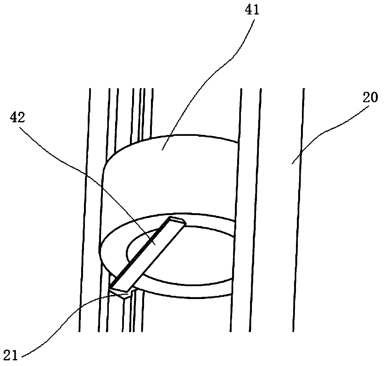
The invention discloses reaction-controllable photocatalytic fiber sewage treatment equipment. A lamplight plate is arranged at the bottom and / or on the side wall of a treatment tank, a frame body, adriving assembly and a cutting assembly are arranged above the treatment tank, the driving assembly and the cutting assembly are connected with the frame body, and a first air bag wraps photocatalyticfibers in the circumferential direction and controls the photocatalytic fibers to move towards the cutting assembly; a second air bag is arranged between the first air bag and the treatment tank andcan obliquely rotate for an angle, a cutter is arranged between the second air bag and the treatment tank and is attached to the end face of the second air bag, the second air bag wraps the photocatalytic fibers in the circumferential direction and controls the photocatalytic fibers to be tightened or loosened, and when one end faces of the photocatalytic fibers stretch out of the end face of thesecond air bag and the photocatalytic fibers are tightened, the cutter cuts along the end face of the second air bag. Sewage is treated through photocatalytic fiber granulation, fiber particles are easy to recover, and the contact area of the photocatalytic fibers and sewage is easy to control, so that the catalytic decomposition rate is controlled, and the control of sewage treatment is realized.

Description

technical field [0001] The invention relates to the technical field of catalytic reaction control, in particular to a reaction-controllable photocatalytic fiber sewage treatment equipment and a use method thereof. Background technique [0002] Sewage treatment is the process of making sewage meet specific discharge standards, or the water quality required for reuse. With the increasing shortage of water resources and the gradual increase of water pollution, sewage treatment has become an important way of water resource protection. [0003] A photocatalyst is a substance that does not change itself under the irradiation of light, but can promote chemical reactions. Photocatalyst converts light energy into chemical reaction energy, produces catalysis, and excites surrounding water molecules and oxygen into highly oxidative hydroxyl radicals and superoxide ion radicals, which can decompose organic substances that are harmful to the human body and the environment. Substances a...

Claims


Application Information

Patent Timeline
Patent Type & Authority Applications(China)
IPC IPC(8): C02F1/30
CPCC02F1/30C02F2201/002
Inventor 张国基张希兰汤燕雯赵甜
Owner FOSHAN JINJINGCHUANG ENVIRONMENTAL PROTECTION TECH CO LTD
Learn More