
Ultrasonic cavitation bubble motion vector estimation method

A technology of motion vectors and cavitation bubbles, applied in ultrasonic therapy, analyzing fluids using sound waves/ultrasonic waves/infrasonic waves, and analyzing solids using sound waves/ultrasonic waves/infrasonic waves. In order to achieve the effects of improving imaging speed, reducing cavitation imaging time, high spatial resolution and signal-to-noise ratio

Pending Publication Date: 2020-06-02
ZHONGBEI UNIV
View PDF7 Cites 1 Cited by
  • Summary
  • Abstract
  • Description
  • Claims
  • Application Information

AI Technical Summary

Problems solved by technology

[0006] The purpose of the present invention is to provide a method for estimating the motion vector of ultrasonic cavitation bubbles to solve the problem that the above-mentioned optical method cannot realize the research on the motion characteristics of cavitation bubbles in non-transparent media, especially in the clinical application of ultrasound therapy such as focused ultrasound therapy. Real-time monitoring of the transient motion characteristics of cavitation bubbles; there are many requirements for the position of the target object and the angle of light acquisition. At the same time, due to the small size of cavitation bubbles, high-speed photography and microscopes are generally required. The randomness of the spatial position makes it difficult to ensure that the observed cavitation bubbles are always on the focal plane of the microscope, etc.

Method used


Image

  • Ultrasonic cavitation bubble motion vector estimation method
  • Ultrasonic cavitation bubble motion vector estimation method
  • Ultrasonic cavitation bubble motion vector estimation method

Examples


preparation example Construction

[0067] Wherein, in step 3, the wide-beam minimum variance beamforming method based on compressed sensing includes the following steps:

[0068] (1) Obtain the number of array elements required according to the dynamic aperture, denoted as M;

[0069] (2) Calculate the delay of the radio frequency signal at different depth points to obtain the delayed signal RF(t);

[0070] RF(t)=[rf 1 (t)rf 2 (t) … rf M (t)] T

[0071] (3) Perform Fourier transform on RF(t) to obtain RF(w);

[0072] RF(w)=[rf 1 (w)rf 2 (w) … rf M (w)] T

[0073] (4) According to the ultrasonic center frequency and its relative bandwidth, select the effective bandwidth w k , K is the number of frequency points within the effective bandwidth, then the corresponding covariance matrix is ​​used as the frequency domain signal RF(w k ),k=1,2,...,K;

[0074] (5) In the effective bandwidth w kThe diagonal matrix T whose dimension is K×K is constructed as the extraction matrix, the elements on the diagona...


PUM


Abstract

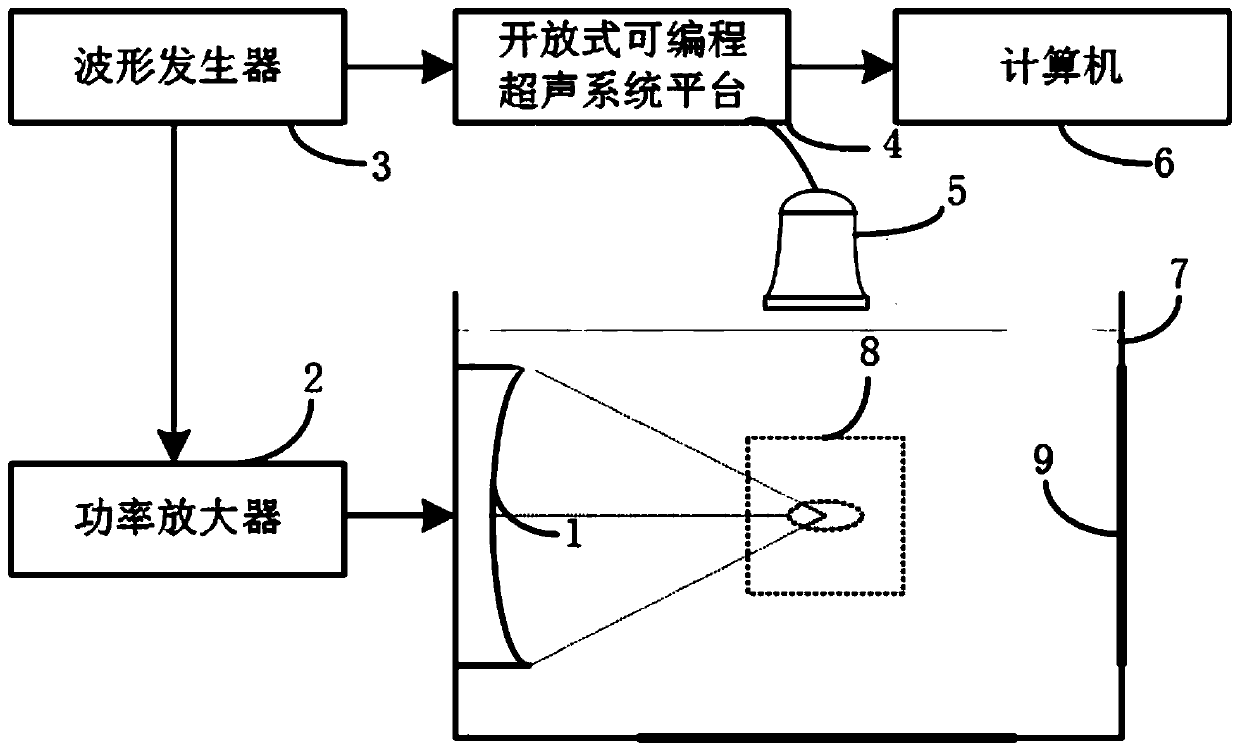
The invention provides an ultrasonic cavitation bubble motion vector estimation method. The ultrasonic cavitation bubble motion vector estimation method comprises the steps of 1, adopting a focused ultrasonic system as a cavitation energy source to generate ultrasonic cavitation bubbles; 2, detecting the ultrasonic cavitation bubbles by transmitting the array wide beams, and acquiring to obtain the continuous sequence ultrasonic cavitation original radio frequency signals; 3, obtaining the continuous N frames of ultrasonic cavitation images by adopting a wide beam minimum variance beam formingalgorithm based on compressed sensing and an ultrasonic imaging algorithm of radio frequency data; 4, performing motion vector estimation on the ultrasonic cavitation image through a pyramid LK optical flow method to form a cavitation bubble motion vector diagram of continuous frames; and 5, changing the parameters and a medium of the focused ultrasound energy source generating cavitation, and repeating the steps 1 to 4 to obtain the cavitation and cavitation motion vector estimation images under different conditions. The invention provides a vector estimation method which is high in temporal-spatial resolution and signal-to-noise ratio and is capable of carrying out transient motion vector estimation on the ultrasonic cavitation bubbles under various conditions and realizing the ultrasonic cavitation bubble motion tracking.

Description

technical field [0001] The present invention relates to the field of acoustic cavitation physics and application and ultrasonic imaging technology. In particular, the method combines the array wide-beam cavitation imaging technology, the wide-beam minimum variance beamforming algorithm based on compressed sensing and the pyramid LK optical flow method. The transient motion vector estimation of the ultrasonic cavitation bubble under the above conditions is realized to realize the motion tracking of the ultrasonic cavitation bubble. Background technique [0002] Acoustic cavitation refers to a series of dynamic processes such as vibration, growth, shrinkage and even collapse of cavitation nuclei in the medium under the action of ultrasonic waves. Ultrasound is widely used in various fields mainly because of its cavitation and its accompanying mechanical effects, thermal effects, chemical effects, biological effects, etc. Acoustic cavitation is also a key physical mechanism in...

Claims


Application Information

Patent Timeline
Patent Type & Authority Applications(China)
IPC IPC(8): G01N29/02G01N29/04G01N29/44A61N7/00
CPCG01N29/02G01N29/045G01N29/44A61N7/00
Inventor 丁婷田志鑫张鹏程田淑爱
Owner ZHONGBEI UNIV
Learn More