Wind power generation boosting transformer and power transformation system for wind power direct-current power transmission and transformation

A technology of step-up transformer and output terminal is applied in the field of power transmission and transformation, which can solve the problems of unfavorable wind power projects, such as grid parity, long transmission cables, and large AC loss.

Pending Publication Date: 2020-06-02
HAINAN JINPAN INTELLIGENCE TECH CO LTD +1
0 Cites 0 Cited by

AI-Extracted Technical Summary

Problems solved by technology

However, since wind power generators are often located on relatively open land or sea, the transmission cables are long, and the loss of AC power during long-distance transmission is large, so that the wind farm project needs to invest a lot o...

Method used

In order to realize the medium and high frequency of transformer, on the basis of the foregoing embodiments, in the wind power generation step-up transformer provided by the embodiment of the present invention, each high-voltage coil adopts multi-strand wires to be wound in parallel, thereby reducing eddy current loss, Adapt to higher frequency voltages.
In specific implementation, the wind power generation step-up transformer 100 provided by the embodiment of the present invention is used in conjunction with the rectifier bridge 200 of the frequency converter, and the quantity of the rectifier of the rectifier bridge 200 is identical with the quantity of the high voltage coil of the wind power generation step-up transformer 100 , and a rectifier is connected to a high-voltage coil, and each phase-shift angle is rectified into a DC by a rectifier bridge 200 and then connected in series, effectively reducing grid harmonics. After the alternating current is converted into direct current for transmission, it can be boosted to 30kV (or 10kV, 35kV, etc.).
In the wind power transmission and transformation project in the prior art, a double-winding transformer is usually used to carry out variable voltage transmission to alternating current, but the loss of alternating current in the process of long-distance power transmission is relatively high, and the use of direct current transmission will greatly reduce the long-distance power transmission Loss in the process, in order to realize DC transmission, the wind power generation step-up transformer provided by the embodiment of the present invention includes an iron core, more than two high-voltage coil...

Abstract

The invention discloses a wind power generation boosting transformer, which comprises an iron core, two or more high-voltage coils arranged at the output end and a low-voltage coil arranged at the input end, wherein the high-voltage coils respectively correspond to different phase shift angles, so that the harmonic wave of the output voltage is reduced, direct-current power transmission is realized by matching with a rectifier. Compared with the prior art in which a double-winding transformer is usually adopted to carry out voltage transformation transmission on alternating current in a wind power transmission and transformation project and the loss is high, the loss of a wind power generation system is greatly reduced by realizing direct current transmission, so that a compensation deviceand a booster station do not need to be arranged on a wind power transmission and transformation line, and the cost of a wind power plant project is reduced. Furthermore, the frequency of the wind power generation boosting transformer is improved through the modes that high-voltage coils are formed by winding multiple strands of wires in parallel, iron cores are made of high-permeability magneticmaterials and the like, so that the cost of the wind power generation system is further reduced. The invention further discloses a power transformation system for wind power direct-current power transmission and transformation, which has the above beneficial effects.

Application Domain

Transformers/inductances coils/windings/connectionsWind motor combinations +2

Technology Topic

Transformation systemsRectiformer +7

Image

  • Wind power generation boosting transformer and power transformation system for wind power direct-current power transmission and transformation
  • Wind power generation boosting transformer and power transformation system for wind power direct-current power transmission and transformation
  • Wind power generation boosting transformer and power transformation system for wind power direct-current power transmission and transformation

Examples

  • Experimental program(1)

Example Embodiment

[0024] The core of the present invention is to provide a wind power step-up transformer and a wind power DC transmission and transformation system, which is used to reduce the loss in the process of wind power transmission, and there is no need to set up compensation devices and booster stations on the wind power transmission and transformation lines. , To reduce the cost of wind farm projects.
[0025] The technical solutions in the embodiments of the present invention will be clearly and completely described below in conjunction with the accompanying drawings in the embodiments of the present invention. Obviously, the described embodiments are only a part of the embodiments of the present invention, rather than all the embodiments. Based on the embodiments of the present invention, all other embodiments obtained by those of ordinary skill in the art without creative work shall fall within the protection scope of the present invention.
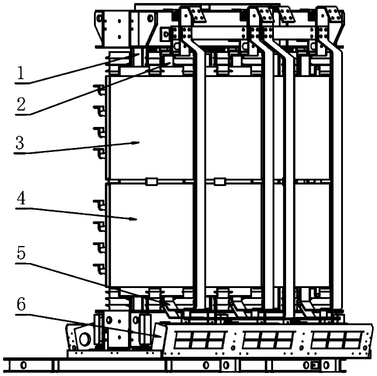
[0026] figure 1 This is a schematic structural diagram of a step-up transformer for wind power generation provided by an embodiment of the present invention.
[0027] Such as figure 1 As shown, the step-up transformer for wind power generation provided by the embodiment of the present invention includes an iron core, two or more high-voltage coils at the output end, and a low-voltage coil at the input end;
[0028] Among them, each high-voltage coil corresponds to a different phase shift angle.
[0029] In specific implementation, such as figure 1 As shown, the step-up transformer for wind power generation provided by the embodiment of the present invention has a three-phase three-column iron core structure, including a three-phase three-column iron 1, a high-voltage coil and a low-voltage coil, and a cooling fan 6 is provided at the bottom. In practical applications , The low-voltage coil at the input end is connected to the wind power generation system through the wind turbine converter, and the high-voltage coil at the output end is connected to the rectifier circuit, and then enters the DC transmission system.
[0030] The wind power step-up transformer provided by the embodiment of the present invention is provided with more than two high-voltage coils, and these high-voltage coils can be divided into two upper and lower high-voltage coil groups, such as figure 1 The high-voltage coil group 3 and the high-voltage coil group 4 are shown. That is, if the wind power step-up transformer is equipped with 8 high-voltage coils and 2 high-voltage coil groups, one high-voltage coil group contains 4 high-voltage coils. And these 8 high voltage coils can also be provided with 8 high voltage coil groups. The number of high-voltage coil groups is not limited to two. For example, if the number of high-voltage coils is 9, three high-voltage coil groups can be set, and each high-voltage coil group includes three high-voltage coils.
[0031] The number of low-voltage coils can also be multiple, and the low-voltage coils are arranged in an axial direction, and the low-voltage coils are connected in parallel. The specific implementation method can be parallel connection during internal winding or external parallel connection. By arranging multiple low-voltage coils, the impedance imbalance of the winding corresponding to each phase shift angle can be effectively reduced. However, the more the number of low-voltage coils, the higher the cost. Therefore, it is preferable to set 2 low voltage coils, such as figure 1 The low-voltage coil 2 and the low-voltage coil 5 shown can ensure the lowest cost under the premise that the impedance imbalance of each output winding is not greater than 8%. Corresponding to the two low-voltage coils, two high-voltage coil groups are provided to facilitate the wiring and assembly of the transformer.
[0032] Based on the above structure and the design of the number of coil turns, it can be ensured that the no-load voltage of each output winding is within ±0.5% of the rated voltage, and the phase shift angle error of the output is within ±0.5°.
[0033] In addition, to ensure insulation, both the high-voltage coil and the low-voltage coil can be casted with epoxy resin.
[0034] In the prior art wind power transmission and transformation projects, dual-winding transformers are usually used to transform AC power. However, the loss of AC power during long-distance transmission is relatively high, and the use of DC transmission will greatly reduce the long-distance transmission process. Loss, in order to realize DC transmission, the wind power step-up transformer provided by the embodiment of the present invention includes an iron core, two or more high-voltage coils at the output end and a low-voltage coil at the input end; wherein each high-voltage coil corresponds to a different shift Phase angle, through two or more high voltage coils corresponding to different phase shift angles, the harmonics of the output current can be reduced, so that the rectifier can be combined to realize the DC transmission without compensating devices and booster stations on the wind power transmission and transformation line, which reduces The cost of wind farm projects.
[0035] figure 2 Is a schematic structural diagram of a high-voltage coil group of a wind power step-up transformer provided by an embodiment of the present invention; image 3 It is a schematic structural diagram of another high-voltage coil group of a wind power step-up transformer provided by an embodiment of the present invention.
[0036] On the basis of the foregoing embodiment, in the wind power step-up transformer provided by the embodiment of the present invention, such as figure 2 with image 3 As shown, the three-phase high voltage of the high voltage coil can adopt the extended-side triangle connection method, and the number of high voltage coils is preferably 8.
[0037] In specific implementation, such as figure 2 with image 3 As shown, the phase shift angles corresponding to each high voltage coil can be +3.75°, -3.75°, +11.25°, -11.25°, +18.75°, -18.75°, +26.25°, -26.25°, respectively.
[0038] Among them, in the high voltage coil of +3.75°, A1'X1 is the main winding of phase A, A1 A1' is the phase shift winding of phase A, B1'Y1 is the main winding of phase B, and B1 B1' is the phase shift of B Phase winding, C1'Z1 is the main winding of phase C, C1 C1' is the phase shift winding of phase C, through figure 2 The shown connection mode realizes a positive phase shift angle, and further realizes a +3.75° phase shift angle through the distribution of winding turns.
[0039] In the +11.25° high voltage coil, A2'X2 is the main winding of phase A, A2 A2' is the phase-shift winding of phase A, B2'Y2 is the main winding of phase B, and B2 B2' is the phase-shift winding of phase B , C2'Z2 is the C-phase main winding, C2 C2' is the C-phase phase-shift winding, through such as figure 2 The shown connection mode realizes a positive phase shift angle, and further realizes a phase shift angle of +11.25° through the distribution of the number of winding turns.
[0040] In the high voltage coil of +18.75°, A3'X3 is the main winding of phase A, A3 A3' is the phase-shift winding of phase A, B3'Y3 is the main winding of phase B, and B3 B3' is the phase-shift winding of phase B , C3'Z3 is the C-phase main winding, C3 C3' is the C-phase phase-shifting winding, through such as figure 2 The shown connection method realizes a positive phase shift angle, and further realizes a phase shift angle of +18.75° through the distribution of the number of winding turns.
[0041] In the +26.25° high-voltage coil, A4'X4 is the main winding of phase A, A4 A4' is the phase-shift winding of phase A, B4'Y4 is the main winding of phase B, and B4 B4' is the phase-shift winding of phase B , C4'Z4 is the C-phase main winding, C4 C4' is the C-phase phase-shift winding, through such as figure 2 The shown connection mode realizes a positive phase shift angle, and then realizes a phase shift angle of +26.25° through the distribution of winding turns.
[0042] In the high voltage coil of -26.25°, A5'X5 is the main winding of phase A, A5 A5' is the phase-shift winding of phase A, B5'Y5 is the main winding of phase B, and B5 B5' is the phase-shift winding of phase B , C5'Z5 is the main winding of phase C, C5 C5' is the phase shift winding of phase C, through such as image 3 The shown connection mode realizes a positive phase shift angle, and further realizes a +3.75° phase shift angle through the distribution of winding turns.
[0043] In the high voltage coil of -18.75°, A6'X6 is the main winding of phase A, A6 A6' is the phase-shift winding of phase A, B6'Y6 is the main winding of phase B, and B6 B6' is the phase-shift winding of phase B , C6'Z6 is the C-phase main winding, C6 C6' is the C-phase phase-shift winding, through such as image 3 The shown connection mode realizes a positive phase shift angle, and then realizes a phase shift angle of +11.25° through the distribution of the number of winding turns.
[0044] In the -11.25° high voltage coil, A7'X7 is the main winding of phase A, A7 A7' is the phase-shift winding of phase A, B7'Y7 is the main winding of phase B, and B7 B7' is the phase-shift winding of phase B , C7'Z7 is the C-phase main winding, C7 C7' is the C-phase phase-shifting winding, through such as image 3 The shown connection method realizes a positive phase shift angle, and further realizes a phase shift angle of +18.75° through the distribution of the number of winding turns.
[0045] In the -3.75° high voltage coil, A8'X8 is the main winding of phase A, A8 A8' is the phase-shift winding of phase A, B8'Y8 is the main winding of phase B, and B8 B8' is the phase-shift winding of phase B , C8'Z8 is the C-phase main winding, C8 C8' is the C-phase phase-shift winding, through such as image 3 The shown connection mode realizes a positive phase shift angle, and further realizes a phase shift angle of +26.25° through the distribution of winding turns.
[0046] Further, combine figure 2 with image 3 In the step-up transformer for wind power generation, the high-voltage coil of +3.75°, the high-voltage coil of +11.25°, the high-voltage coil of +18.75°, the high-voltage coil of +26.25° and the high-voltage coil of -3.75°, the high-voltage wire of -11.25° respectively The high-voltage coils of -18.75° and the high-voltage coils of -26.25° are arranged in axial symmetry.
[0047] As mentioned in the above embodiment, 8 high-voltage coils can be provided with 2 high-voltage coil groups, then the high-voltage coil of +3.75°, the high-voltage coil of +11.25°, the high-voltage coil of +18.75° and the high-voltage coil of +26.25° form the first A high-voltage coil group, -3.75° high-voltage coil, -11.25° high-voltage coil, -18.75° high-voltage coil and -26.25° high-voltage coil form the second high-voltage coil group, corresponding to figure 1 The high-voltage coil group 3 and the high-voltage coil group 4 in the middle, correspondingly, the number of low-voltage coils is specifically two, corresponding to figure 1 In the low-voltage coil 2 and the low-voltage coil 5.
[0048] On the basis of the above embodiments, those skilled in the art can design according to actual needs, such as changing the connection mode of high voltage and low voltage, changing the series-parallel relationship, the number of low voltage coils, the number of high voltage phase shift angles, the phase shift connection mode, The material of the iron core, the encapsulation form of the transformer winding, etc. fall within the protection scope of the embodiment of the present invention.
[0049] The step-up transformer for wind power generation provided in the above embodiments is not only suitable for the field of wind power transmission and transformation, but also for electric locomotives and other fields, and in these fields, the volume and weight of the transformer are highly restricted. In response to the user's requirements for reducing the size and cost of dry-type transformers, if a traditional power frequency 50Hz/60Hz transformer is used, measures such as increasing the impedance of the transformer and increasing the temperature rise are mainly used. With the increasing capacity of transformers, this method will become increasingly difficult to meet the relevant size and weight requirements. Therefore, on the basis of the foregoing embodiments, in the embodiments of the present invention, in order to further reduce the cost of the wind farm project, the miniaturization of the transformer is realized from the perspective of realizing the medium and high frequency of the transformer.
[0050] In order to realize the medium and high frequency of the transformer, on the basis of the above-mentioned embodiment, in the wind power step-up transformer provided by the embodiment of the present invention, each high-voltage coil is wound with multiple strands, thereby reducing the eddy current loss and improving the adaptation. High frequency voltage.
[0051] Further, the iron core is made of high-permeability silicon steel sheet material or amorphous alloy material or nanocrystalline material, which can also effectively reduce eddy current loss and adapt to higher frequency voltage.
[0052] The step-up transformer for wind power generation provided by the embodiment of the present invention realizes medium and high frequency, and can operate at full capacity in the medium frequency range of 100 Hz-1000 Hz.
[0053] The respective embodiments corresponding to the step-up transformer for wind power generation are described in detail above. On this basis, the present invention also discloses a wind power DC transmission and transformation system corresponding to the above-mentioned step-up transformer for wind power generation.
[0054] Figure 4 It is a wind power DC transmission and transformation system provided by an embodiment of the present invention.
[0055] Such as Figure 4 As shown, the wind power DC transmission and transformation provided by the embodiment of the present invention includes the wind power step-up transformer 100 described in any one of the above embodiments, and also includes a rectifier bridge 200 connected to the wind power step-up transformer 100;
[0056] Wherein, the input end of the wind power step-up transformer 100 is connected to the output end of the wind power system, the output end of the wind power step-up transformer 100 is connected to the input end of the rectifier bridge 200, and the output end of the rectifier bridge 200 is connected to the DC power transmission system;
[0057] The number of rectifiers of the rectifier bridge 200 is the same as the number of high-voltage coils of the wind power step-up transformer 100, and one rectifier is connected to one high-voltage coil.
[0058] In specific implementation, the wind power step-up transformer 100 provided by the embodiment of the present invention is used in conjunction with the rectifier bridge 200 of the frequency converter. The number of rectifier bridges 200 is the same as the number of high-voltage coils of the wind power step-up transformer 100, and one The rectifier is connected with a high-voltage coil, and each phase shift angle passes through the rectifier bridge 200 and then rectified into direct current and then connected in series, effectively reducing the harmonics of the power grid. The alternating current is converted into direct current for transmission and can be boosted to 30kV (or 10kV, 35kV, etc.).
[0059] To further increase the transmission voltage, such as Figure 4 As shown, a symmetrical structure is adopted and the wind power generation step-up transformer 100 and the rectifier bridge 200 provided by the embodiment of the present invention are used to design two sets of substation structures. The ground ends of the two sets of structures are connected to 0V, and the other end is connected to a transmission cable. They are respectively 30kV and -30kV, thus realizing the 60kV DC transmission of the whole system.
[0060] In the above, a wind power step-up transformer and a wind power DC transmission and transformation system provided by the present invention have been introduced in detail. The various embodiments in the specification are described in a progressive manner, and each embodiment focuses on the differences from other embodiments, and the same or similar parts between the various embodiments can be referred to each other. It should be pointed out that for those of ordinary skill in the art, without departing from the principle of the present invention, several improvements and modifications can be made to the present invention, and these improvements and modifications also fall within the protection scope of the claims of the present invention.
[0061] It should also be noted that in this specification, relational terms such as first and second are only used to distinguish one entity or operation from another entity or operation, and do not necessarily require or imply these entities or operations. There is any such actual relationship or sequence between operations. Moreover, the terms "include", "include" or any other variants thereof are intended to cover non-exclusive inclusion, so that a process, method, article, or device that includes a series of elements includes not only those elements, but also includes Other elements of, or also include elements inherent to this process, method, article or equipment. If there are no more restrictions, the element defined by the sentence "including a..." does not exclude the existence of other same elements in the process, method, article, or equipment that includes the element.

PUM

no PUM

Description & Claims & Application Information

We can also present the details of the Description, Claims and Application information to help users get a comprehensive understanding of the technical details of the patent, such as background art, summary of invention, brief description of drawings, description of embodiments, and other original content. On the other hand, users can also determine the specific scope of protection of the technology through the list of claims; as well as understand the changes in the life cycle of the technology with the presentation of the patent timeline. Login to view more.
Why Eureka
Try Eureka