Machining device for mechanical arm

A technology of processing equipment and manipulators, applied in metal processing equipment, metal processing, metal processing machinery parts, etc., can solve problems such as low processing efficiency, achieve the effects of improving processing efficiency, improving stability, and improving refueling efficiency

Active Publication Date: 2020-06-05
杭州现代机械有限公司
View PDF14 Cites 6 Cited by
  • Summary
  • Abstract
  • Description
  • Claims
  • Application Information

AI Technical Summary

Problems solved by technology

[0004] However, during the cutting process of the steel pipe, workers are required to measure and mark the cutting place of the steel pipe, and then the steel pipe is cut multiple times by a cutting machine; during the drilling process of the steel pipe, workers are required to measure the drilled part of the steel pipe mark, and then use the drilling machine to drill the steel pipe multiple times, so the processing of each group of steel pipes takes 3 to 5 minutes, and the processing efficiency is relatively low, so it needs to be improved

Method used


Image

  • Machining device for mechanical arm
  • Machining device for mechanical arm
  • Machining device for mechanical arm

Examples


Embodiment Construction

[0044] The present invention will be described in further detail below in conjunction with the accompanying drawings.

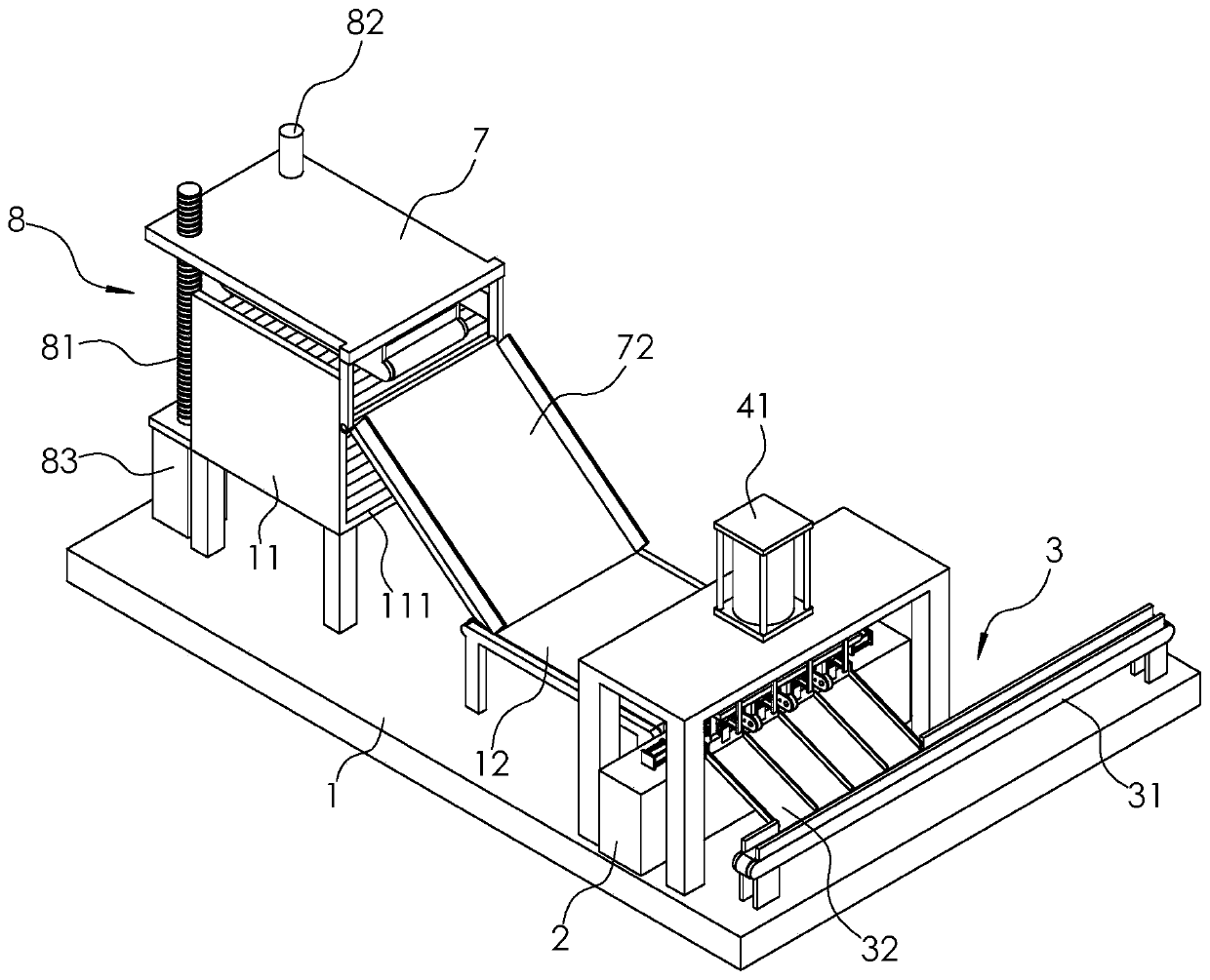
[0045] Such as figure 1 As shown, a processing equipment for manipulators includes a frame 1, a shelving frame 11 arranged in sequence along the horizontal direction, a first inclined frame 72, a first conveyor belt 12, a workbench 2, a blanking assembly 3 and a second conveyor belt 31.

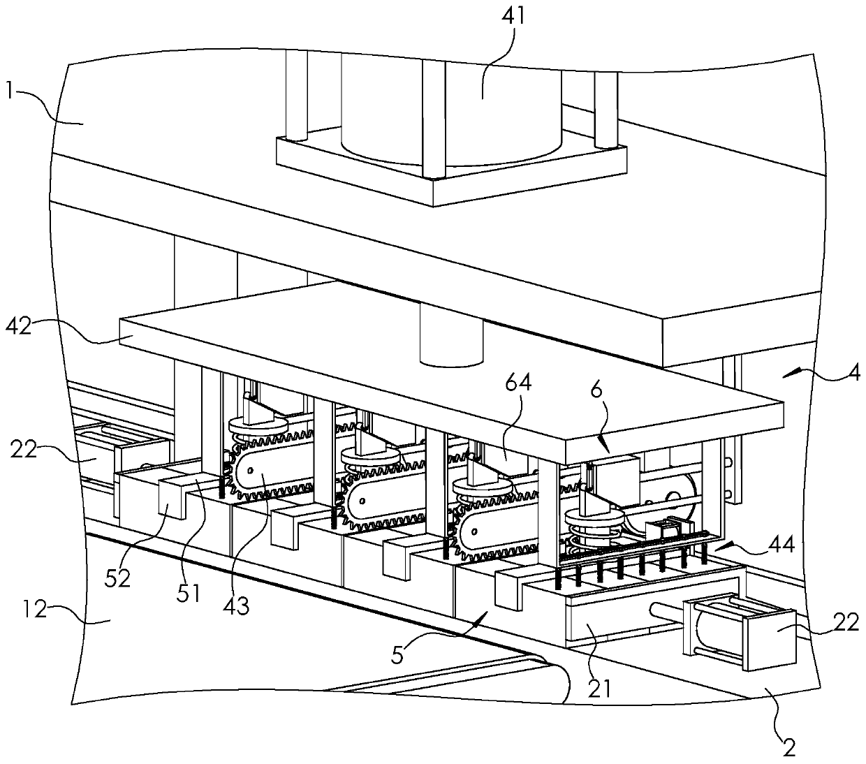
[0046] Such as figure 1 and figure 2 As shown, the extension direction of the workbench 2 is perpendicular to the conveying direction of the first conveyor belt 12, and both ends of the workbench 2 are provided with a pressing plate 21 and a driving part, and the driving part is the second one fixed on the frame 1. The cylinder 22 , the piston rod of the second cylinder 22 is fixedly connected to the pressing plate 21 . After multiple sets of steel pipes on the shelf 11 are transported to the workbench 2 by the first conveyor belt 12, the second cylinder 22 will drive t...


PUM


Abstract

The invention relates to a machining device for a mechanical arm. The machining device comprises a rack and a first transfer belt, a shelf is arranged at the input end of the first transfer belt, a worktable is arranged at the output end of the first transfer belt, and a discharging assembly is arranged on the side, away from the first transfer belt, of the worktable. The two ends of the worktableare both provided with a withstanding plate and a driving piece, and a plurality of insertion columns are fixed to the sides, facing steel pipes, of the two withstanding plates; a plurality of cutting assemblies, a plurality of drilling assemblies and a plurality of pressing assemblies are arranged on the upper side of the worktable, and the rack is provided with a lifting assembly and a drivingassembly. In the steel pipe machining process, the first transfer belt conveys the steel pipes onto the worktable, the driving pieces drive the withstanding plates to withstand the end portions of thesteel pipes, then the pressing assemblies tightly press the steel pipe, and all the cutting assemblies and drilling assemblies machine the steel pipes. After the steel pipes are cut and drilled, themachined steel pipes are pushed by new steel pipes onto the discharging assembly. By means of the machining device, the steel pipe machining efficiency is greatly improved.

Description

technical field [0001] The invention relates to the technical field of manipulator processing equipment, in particular to a processing equipment used for manipulators. Background technique [0002] A manipulator is an automatic operating device that can imitate certain movement functions of the human hand and arm to grab, carry objects or operate tools according to a fixed program. It is characterized in that it can be programmed to complete various expected operations. Existing manipulators are usually made of square steel pipes, which often need to be cut into several sections and drilled on each section before the steel pipe is used. [0003] The existing steel pipe processing equipment includes a shelf, a platform, a cutting machine and a drilling machine arranged on the platform. Steel pipes are generally stacked on the shelf. During the processing, the worker first takes the steel pipe on the shelf and The steel pipe is pressed tightly on the platform, and then the st...

Claims


Application Information

Patent Timeline
Patent Type & Authority Applications(China)
IPC IPC(8): B23P23/02B23Q3/08B23Q7/00
CPCB23P23/02B23Q3/08B23Q7/00B23Q7/003
Inventor 梁斌
Owner 杭州现代机械有限公司
Why Eureka
Try Eureka