A mixed working medium high-pressure gas liquefaction and subcooling system

A technology of mixing working fluid and high-pressure gas, applied in the directions of liquefaction, refrigeration and liquefaction, cold treatment separation, etc., can solve the problems of poor matching effect and low efficiency of mixed working fluid, and achieve high utilization efficiency of cold energy, simple process structure, and avoidance of The effect of cooling temperature is too low

Active Publication Date: 2021-12-17
TECHNICAL INST OF PHYSICS & CHEMISTRY - CHINESE ACAD OF SCI
View PDF10 Cites 0 Cited by
  • Summary
  • Abstract
  • Description
  • Claims
  • Application Information

AI Technical Summary

Problems solved by technology

[0003] However, for natural gas and other gases to be liquefied with a higher atmospheric boiling point (around -161°C and above), the temperature-load characteristics at the subcooled end are linear due to the liquid-phase sensible heat release playing a leading role, which matches the mixed working fluid. The effect is poor, resulting in low efficiency, so it is necessary to set up an additional process structure to optimize the matching of the subcooling section

Method used


Image

  • A mixed working medium high-pressure gas liquefaction and subcooling system
  • A mixed working medium high-pressure gas liquefaction and subcooling system
  • A mixed working medium high-pressure gas liquefaction and subcooling system

Examples


Embodiment 1

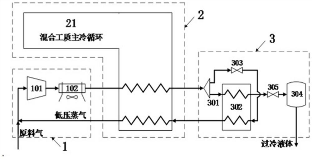
[0025] see figure 1 , is a mixed working medium high-pressure gas liquefaction and supercooling system provided in Embodiment 1 of the present invention, including: a gas pressurization unit 1 , a mixed working medium refrigerator unit 2 , and a supercooling unit 3 . in:

[0026] The gas booster unit 1 includes a gas compressor 101 and an aftercooler 102 .

[0027] It can be understood that a multi-stage compressor can be used to mix the low-pressure feed gas and low-pressure steam to pressurize to 10-30 bar.

[0028] The mixed working medium refrigerator unit 2 includes a mixed working medium main refrigeration cycle 21 .

[0029] The subcooling unit 3 includes a distributor 301 , a subcooling heat exchanger 302 , a main throttling element 303 , a liquid storage tank 304 and a liquefied gas throttling element 305 .

[0030] The working mode of the mixed working medium high-pressure gas liquefaction and supercooling system provided by the above-mentioned embodiment 1 of the...

Embodiment 2

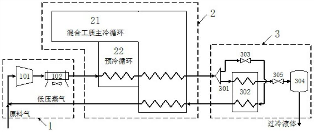
[0035] see figure 2 , is a schematic structural diagram of the mixed working medium high-pressure gas liquefaction and supercooling system provided by Embodiment 2 of the present invention. For the convenience of description, only the relevant drawings are described below.

[0036] The difference from the above-mentioned embodiment 1 is that the mixed working medium refrigerator unit provided in the second embodiment of the present invention also includes a pre-cooling cycle 22, which pre-cools the high-pressure feed gas and the mixed working medium; the pre-cooling The cycle 22 can adopt configurations such as a vapor compression refrigeration cycle, an absorption refrigeration cycle, and a commercial chiller.

[0037] For other working methods, refer to Embodiment 1, which will not be repeated here.

[0038]The mixed working medium high-pressure gas liquefaction and supercooling system provided by the above-mentioned embodiment 2 of the present invention uses a precooling ...

Embodiment 3

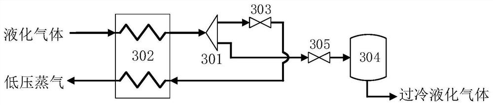
[0040] see image 3 , is a schematic structural diagram of the mixed working medium high-pressure gas liquefaction and supercooling system provided by Example 4 of the present invention.

[0041] The liquefied gas formed by cooling the high-pressure feed gas through the mixed working medium refrigerator unit 2 is firstly subcooled to -150°C to -190°C through the subcooling heat exchanger 302, and then passed through the gas distributor 301 separates a small stream of liquefied gas, the small stream of liquefied gas is throttled by the main throttling element 303 to close to normal pressure and cooled to below -152°C to -192°C, and then enters the subcooling heat exchanger 302. Liquefaction provides cooling capacity and forms low-pressure steam, and then returns to the gas compressor 101 after being reheated by the mixed working medium refrigerator unit 2 and recovering cooling capacity, and continues to participate in liquefaction;

[0042] The remaining liquefied gas separat...


PUM


Abstract

The mixed working medium high-pressure gas liquefaction and supercooling system provided by the present invention includes: a gas pressurization unit, a mixed working medium refrigerator unit and a supercooling unit. The gas pressurization unit includes a gas compressor and an aftercooler. The mixed working medium refrigerator unit includes a mixed working medium main cooling cycle, and the described supercooling unit includes a subcooling heat exchanger, a throttling element and a liquid storage tank. Distributed cooling of the gas, high efficiency of cold energy utilization, and the use of liquefied gas itself for supercooling, avoiding the serious attenuation of efficiency caused by the low cooling temperature of the mixed working medium refrigerator, and at the same time the process structure is relatively simple, no additional supercooling is required refrigerator.

Description

technical field [0001] The invention relates to the technical field of refrigeration and precooling of mixed working fluid, in particular to a mixed working medium high-pressure gas liquefaction and supercooling system. Background technique [0002] Liquefied gases are important industrial products. The greater the degree of subcooling of the gas after liquefaction, the less difficult it is to store and transport the liquefied gas, and the smaller the flash loss during use. Taking nitrogen and oxygen liquefaction as an example, the development of conventional large-scale air separation plants is relatively mature, and it is also the main source of liquefied gas in the market, but its products are mainly gas nitrogen and gas oxygen, and liquid nitrogen and liquid oxygen gas only account for a very small amount of its output some by-products. The production of extremely large quantities of liquefied gas requires a special liquefaction process to pressurize the gas nitrogen t...

Claims


Application Information

Patent Timeline
Patent Type & Authority Patents(China)
IPC IPC(8): F25J1/02
CPCF25J1/0235F25J1/0245F25J1/0045F25J1/004F25J1/0052F25J1/0219F25J2270/906F25J2270/90F25J1/0227F25J1/0022F25J1/0015F25J1/0017F25J2290/34
Inventor 公茂琼王昊成郭浩
Owner TECHNICAL INST OF PHYSICS & CHEMISTRY - CHINESE ACAD OF SCI
Why Eureka
Try Eureka