Ground gathering and conveying system for depleted gas storage

A technology of gathering and transportation system and gas storage, which is applied in the field of ground process flow and equipment to achieve the effects of reducing construction costs, eliminating slug flow, and being easy to operate.

Active Publication Date: 2020-06-09
SINOPEC ZHONGYUAN PETROLEUM ENG DESIGN
View PDF7 Cites 0 Cited by
  • Summary
  • Abstract
  • Description
  • Claims
  • Application Information

AI Technical Summary

Problems solved by technology

At present, there are few reports and studies on the surface gathering and transportation system for depleted gas reservoirs. Therefore, it is necessary to study the surface gathering and transportation technology suitable for underground gas storage of d

Method used


Image

  • Ground gathering and conveying system for depleted gas storage
  • Ground gathering and conveying system for depleted gas storage
  • Ground gathering and conveying system for depleted gas storage

Examples


Embodiment 1

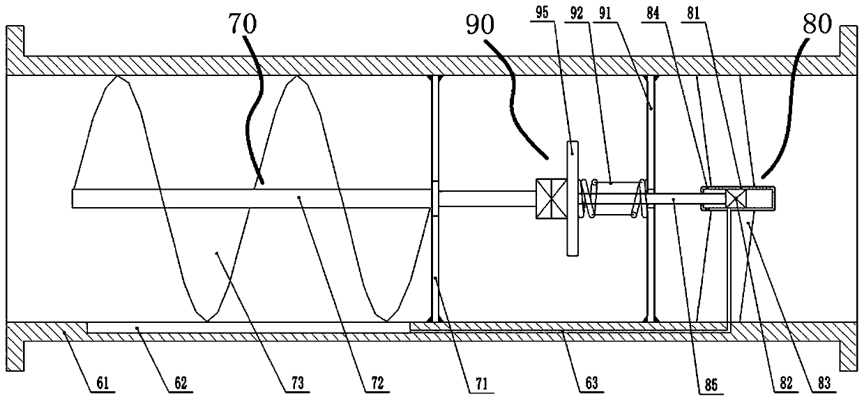
[0073] The pipeline is provided with an effusion controller, and the effusion controller includes a pipe joint 61, which is connected to the pipeline through a flange, and the pipe joint 61 is sequentially provided with a swirl flow generating mechanism 70 from upstream to downstream. , the driving mechanism 90, the spraying mechanism 80, the position corresponding to the swirl flow generating mechanism 70 on the inner wall of the pipe joint 61 is provided with a sump 62, the driving mechanism 90 is connected to the spraying mechanism 80, and the sump 62 is connected to the spraying mechanism through the flow pipe 63 80, the driving mechanism 90 is powered by the swirl generator 70 or natural gas to drive the spraying mechanism 80 to spray the accumulated liquid in the sump 62 into mist and be carried away by the natural gas.

[0074] The swirl mechanism includes a swirl bracket 71 fixedly arranged on the inner wall of the pipe joint 61 , a center shaft 72 is rotated at the cen...

Embodiment 2

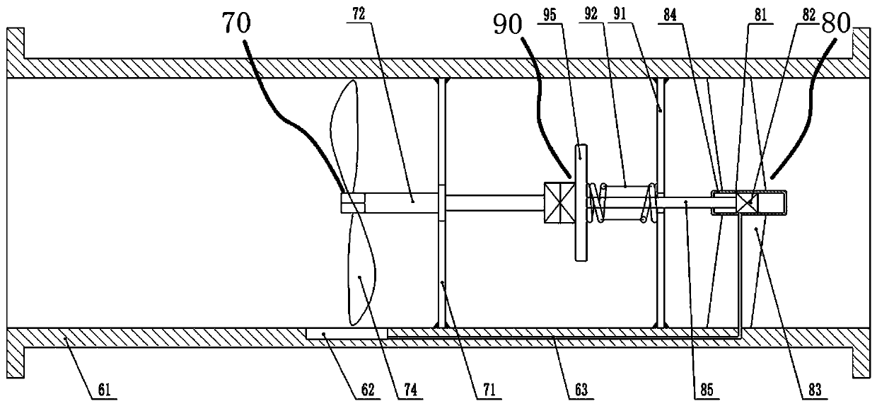
[0079] The difference between this embodiment and Embodiment 1 is that a fan blade 74 is fixedly arranged on the central shaft 72 .

Embodiment 3

[0081] The difference between this embodiment and Embodiment 2 is that the liquid flow pipe 63 is not arranged in the pipe wall of the pipe joint 61 .

[0082] The liquid flow pipe 63 is also communicated with the suppression base liquid tank 66 through the suppression base liquid pipe 64, the suppression base liquid pipe 64 is provided with a one-way valve 65, and the hydrate suppression base liquid in the suppression base liquid tank 66, the hydrate suppression The base fluid is a functionalized dendrimer comprising at least one quaternary ammonium zwitterionic functional end group. The hydrate-inhibiting base fluid needs to be mixed with the effusion, then made into a mist, and then enters the pipeline. The hydrate inhibiting base liquid is mixed and prepared in the liquid flow pipe 63, which makes full use of the accumulated liquid in the pipe, and saves the need to prepare the hydrate inhibiting base liquid and water to make the hydrate inhibitor and then inject it from t...


PUM


Abstract

The invention belongs to the technical field of ground technological process and equipment of an underground gas storage, and particularly relates to a ground gathering and conveying system for a depleted gas storage. The ground gathering and conveying system for the depleted gas storage is installed between a wellhead of the gas storage and an outputting pipeline, and is connected through pipelines and valve groups. The ground gathering and conveying system comprises a slug flow catcher, an air cooler, a cyclone separator, a filtering separator, a triethylene glycol dewatering device, a natural gas compressor, an emptying torch, a metering separator, a produced water storage tank, a wellhead gas production tree, a valve group and an emptying valve group, wherein the valve group and the emptying valve group are arranged on a pipeline, and a liquid accumulation controller is arranged on the pipeline. According to the ground gathering and conveying system for the depleted gas storage, the same set of pipelines and devices are adopted as the gas injection and gas production technological process conveying system for the gas storage, so that the repeated use of the gas injection-gas production pipelines and devices is realized, and the construction amount and the construction cost are greatly reduced.

Description

technical field [0001] The invention belongs to the technical field of surface process flow and equipment of an underground gas storage, and in particular relates to a ground gathering and transportation system for a depleted gas storage gas storage. Background technique [0002] Many natural gas users have a large difference in gas consumption between winter and summer. Generally, the gas consumption in winter is higher than that in summer. In extreme cases, the gas consumption in winter will be 6 to 10 times that in summer. Peak shaving, that is, when the market gas consumption in summer is lower than the pipeline gas transmission capacity, the excess gas is stored in the underground gas storage, and in winter, when the user's gas consumption exceeds the pipeline transmission capacity, natural gas is extracted from the underground gas storage to supply users . In addition, the gas consumption will vary at different times of the day, and the gas storage is also required fo...

Claims


Application Information

Patent Timeline
IPC IPC(8): F17D1/02F17D1/17F17D3/01F17D3/14F17D3/12C10L3/10
CPCC10L3/101C10L3/106C10L3/107F17D1/02F17D1/17F17D3/01F17D3/12F17D3/145
Inventor 高继峰仝淑月孙娟宋世昌周树青陈清涛公明明宋燕
Owner SINOPEC ZHONGYUAN PETROLEUM ENG DESIGN
Why Eureka
Try Eureka