
Device and method for measuring dielectric constant and metal conductivity of copper-clad plate

A technology of dielectric constant and metal conductance, which is applied in the field of microwave measurement, can solve problems such as difficult to meet the demand, uncertain metal conductivity, neglect of metal conductivity, etc.

Inactive Publication Date: 2020-06-09
NORTHWESTERN POLYTECHNICAL UNIV
View PDF12 Cites 4 Cited by
  • Summary
  • Abstract
  • Description
  • Claims
  • Application Information

AI Technical Summary

Problems solved by technology

Some traditional transmission line resonance permittivity measurement methods only measure one parameter, the relative permittivity, which characterizes the permittivity, but do not measure the loss tangent, another parameter that characterizes the permittivity, such as in the literature ([1] Guo Fuxiang, Lai Zhanjun, Xue Fengzhang. Non-destructive measurement of dielectric constant based on microstrip resonance method[J]. Journal of Chongqing University of Posts and Telecommunications (Natural Science Edition), 2017,29(03):346-351.); The loss tangent was measured but it was measured in the case of known metal conductivity, ignoring the influence caused by the uncertainty of metal conductivity, such as in the literature ([1] Xu Zengchao. Stripline resonator method complex dielectric Constant temperature test [D]. University of Electronic Science and Technology of China, 2008.)
For example, in many microwave applications, the conductivity of the metal is uncertain or the conductivity changes due to chemical reactions, roughness and unevenness of the metal surface, etc., which will have a non-negligible impact on microwave applications involving this metal, so traditional The method of extracting the dielectric constant of the dielectric plate has been difficult to meet the demand

Method used


Image

  • Device and method for measuring dielectric constant and metal conductivity of copper-clad plate
  • Device and method for measuring dielectric constant and metal conductivity of copper-clad plate
  • Device and method for measuring dielectric constant and metal conductivity of copper-clad plate

Examples


Embodiment

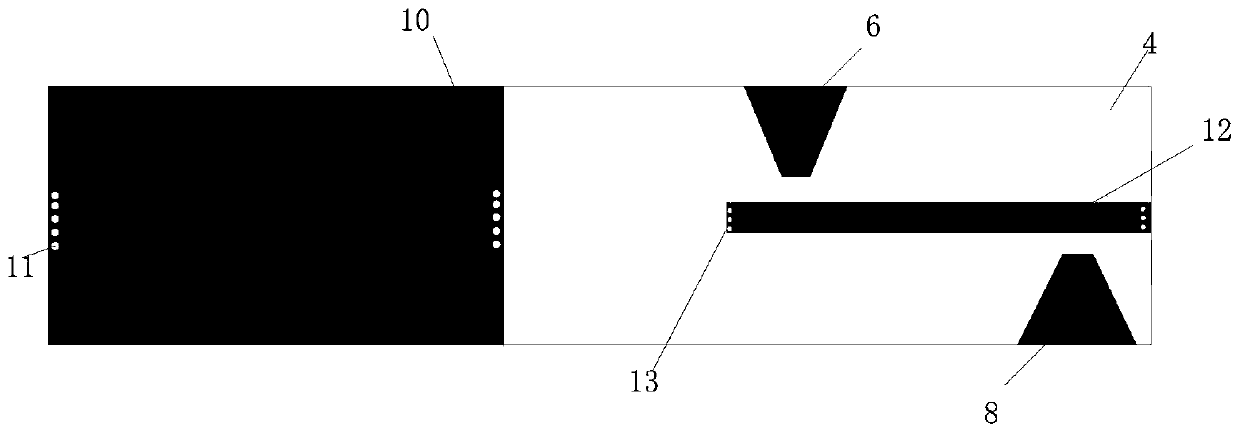
[0129] Such as figure 1 As shown, a microstrip resonant cavity and a parallel double-line resonant cavity are arranged on the copper clad board 4 with a height of 0.5 mm, a width of 10 mm, and a length of 200 mm. The width w of the conduction band 1 of the microstrip line resonator is 2 mm, and the width w of the conduction band 5 on one side of the parallel double-line resonator and the conduction band 12 on the other side of the parallel double-line resonator is 1 mm. The conduction band 1 of the microstrip line resonator, the conduction band 5 on one side of the parallel double lines, and the conduction band 12 on the other side of the parallel double lines all have a thickness t of 0.035 mm and a length L of 73 mm. Depend on figure 2 It can be seen that the microstrip part has a conductor ground 10 with a width of 10mm and a length of 73mm, and the microstrip resonant cavity is fed through a feeding microstrip line 2 and another feeding microstrip line, and the parallel ...


PUM


Abstract

The invention discloses a device and a method for measuring dielectric constant and metal conductivity of a copper-clad plate, and belongs to the field of microwave measuring. The device is characterized in that a microstrip line with two short-circuited ends and a parallel double-line with two short-circuited ends are manufactured on the copper-clad plate to form two resonant cavities respectively, and coupled feeding is performed through the microstrip line; and a vector network analyzer is used for measuring. Because the parameters of the microstrip line and the parallel double-line are different, losses are different, quality factors are different, the conductivity of a metal used by a microstrip line conduction band and the relative dielectric constant and loss tangent of the copper-clad plate material are obtained through the relationship between the quality factors of the microstrip line and the parallel double-line, and the quality factors are obtained through the scattering parameters measured by the vector network analyzer. According to the method, the conductivity of the metal used by the conduction band can be calculated, so that errors caused by uncertainty of the conductivity are reduced, the dielectric constant of the material is measured and calculated, the adaptability is high, the steps for measuring the dielectric constant of the material are greatly simplified, and the method is easy to implement in engineering.

Description

technical field [0001] The invention belongs to the field of microwave measurement, and in particular relates to a measuring device and method for the dielectric constant and metal conductivity of a copper-clad laminate. Background technique [0002] The dielectric constant of a dielectric material is a physical quantity that describes the electrical properties of a dielectric material. It is a basic parameter for analyzing and studying the interaction between electromagnetic waves and dielectric materials and the change of field quantities, and has important physical significance. In engineering, two parameters, relative permittivity and loss tangent, are generally used to characterize the permittivity of materials. When producing and using dielectric materials, accurate acquisition of their dielectric constant is one of the prerequisites for microwave circuit design. At present, the dielectric constant measurement methods of dielectric substrates mainly include lumped cir...

Claims


Application Information

Patent Timeline
IPC IPC(8): G01N27/00G01N27/04G01N27/22G01R27/26
CPCG01N27/00G01N27/041G01N27/221G01R27/2617G01R27/2623
Inventor 吴昌英路少鹏高峰
Owner NORTHWESTERN POLYTECHNICAL UNIV
Learn More