
Manufacturing method of cell fusion photoelectric sensor and working method of imaging system thereof

A photoelectric sensor and cell fusion technology, which is applied to the parts of the TV system, chemical instruments and methods, embryonic cells, etc., can solve problems such as the inability to achieve high-resolution imaging and the difficulty in realizing the array of new photosensitive devices

Inactive Publication Date: 2020-06-09
JIANGNAN UNIV
View PDF3 Cites 1 Cited by
  • Summary
  • Abstract
  • Description
  • Claims
  • Application Information

AI Technical Summary

Problems solved by technology

[0004] The technical problem to be solved by the present invention is to provide a photoelectric sensor for cell fusion and the working method of its imaging system. For the first time, a photoelectric sensor for biological fusion is constructed using living cells as photosensitive units; it is difficult to realize the array of new photosensitive devices in the current technology. The problem of being unable to realize high-resolution imaging, the present invention constructs a single-pixel imaging system based on a single bio-fusion optoelectronic device to achieve high-resolution imaging

Method used


Image

  • Manufacturing method of cell fusion photoelectric sensor and working method of imaging system thereof
  • Manufacturing method of cell fusion photoelectric sensor and working method of imaging system thereof
  • Manufacturing method of cell fusion photoelectric sensor and working method of imaging system thereof

Examples


Embodiment Construction

[0023]The present invention will be further described below in conjunction with the accompanying drawings and specific embodiments, so that those skilled in the art can better understand the present invention and implement it, but the examples given are not intended to limit the present invention.

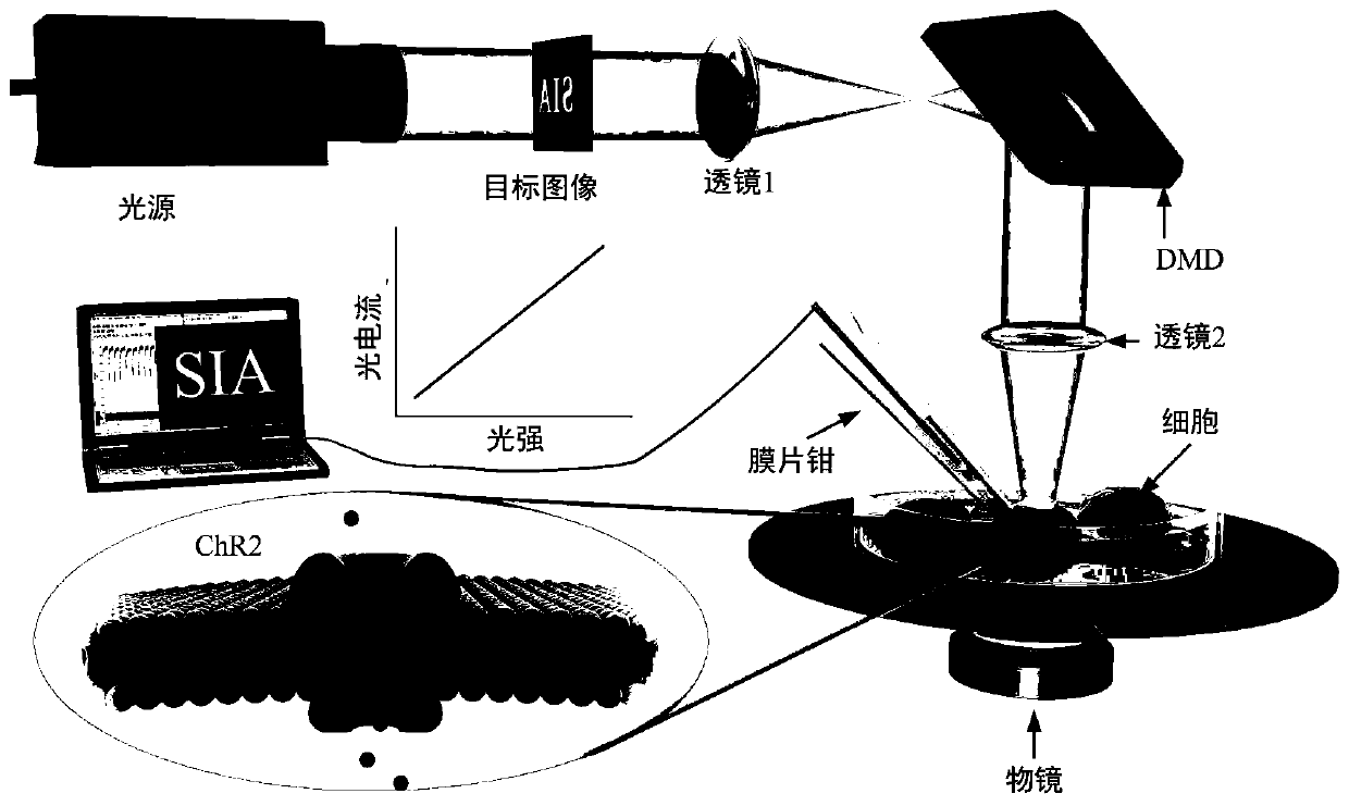
[0024] The invention provides a photoelectric sensor for cell fusion and an imaging system thereof. The photoelectric sensor construction process of cell fusion is as follows: figure 1 shown. Transfect the channelrhodopsin (ChR2) extracted from the eye spot (Eye spot) of Chlamydomonas reinhardtii cells into human embryonic kidney 293 (Hek293, Human embryonic kidney) cells, which have good photosensitivity and pass through the membrane Piece-clamp techniques can detect the light-responsive properties of cells. The specific construction process of this photosensitive cell is: 1) using the proofreading polymerase (primers with BamHI and HindIII restriction sites) with polymerase (pf...


PUM

PropertyMeasurementUnit
wavelengthaaaaaaaaaa

Abstract

The invention discloses a cell fusion photoelectric sensor and a working method of an imaging system of the cell fusion photoelectric sensor. The manufacturing method of the cell fusion photoelectricsensor comprises the following steps: rhodopsin channel protein (ChR2) extracted from a chlamydomonas reinhardtii cell eye spot is transfected into a human embryonic kidney 293 (Hek293) cell; finally,the expression of the ChR2 plasmid in the cell is observed through a fluorescence microscope, and the cell expression result is further verified through photostimulation by using a patch clamp technology; the Hek293 cell expressing ChR2 is used as a sensitive material of a photoelectric sensor, optical signals absorbed by a device are converted into an ionic current by the Hek293 cell, and a patch clamp technology is used as a signal acquisition and processing unit of the photoelectric sensor; and the cell is combined with patch clamp detection equipment to form the cell fusion photoelectricsensor. The biological fusion photoelectric device has the beneficial effects that the biological fusion photoelectric device can fully utilize the advantages of organisms in light perception or vision, so that a novel device with better performance than a pure artificial device is generated.

Description

technical field [0001] The invention relates to the field of photoelectric sensors, in particular to a photoelectric sensor for cell fusion and a working method of an imaging system thereof. Background technique [0002] Biological systems have undergone hundreds of millions of years of evolution and development in nature, and have advantages in structure and functional characteristics that many artificial systems cannot match. Integrating biological cells or tissues with electromechanical systems to build a biological fusion system can make full use of the structural and functional advantages of organisms, thereby creating some more complete structures and more powerful functional characteristics. At present, many organic fusion systems driven or powered by biological living cells or tissues have been reported in many top international journals. Montemagno et al. at the University of California, Los Angeles, cultivated muscle cells in a micromechanical structure, assembled...

Claims


Application Information

Patent Timeline
Patent Type & Authority Applications(China)
IPC IPC(8): H04N5/335C12N15/85C12N15/31C12N5/10G01N33/487H04N25/00
CPCC12N15/85C07K14/405C12N5/0603C12N5/0686G01N33/48728C12N2800/107C12N2510/00H04N25/00
Inventor 李恭新
Owner JIANGNAN UNIV
Learn More