Impeller of oxygen-enriching machine

A technology of aerator and impeller, applied in fish farming, application, animal husbandry, etc., can solve the problems of limited air, short contact time between water and air, poor oxygenation effect, etc., to improve fluidity, reduce resistance, the effect of reducing drive power requirements

Pending Publication Date: 2020-06-12
郑卫兵
View PDF1 Cites 5 Cited by
  • Summary
  • Abstract
  • Description
  • Claims
  • Application Information

AI Technical Summary

Problems solved by technology

However, although the impeller of the aerator can push a large amount of water to move, the contact time between the water body and the air is short, and the air that can actually enter the water body is limited, resulting in poor oxygenation effect

Method used


Image

  • Impeller of oxygen-enriching machine
  • Impeller of oxygen-enriching machine
  • Impeller of oxygen-enriching machine

Examples


Embodiment 1

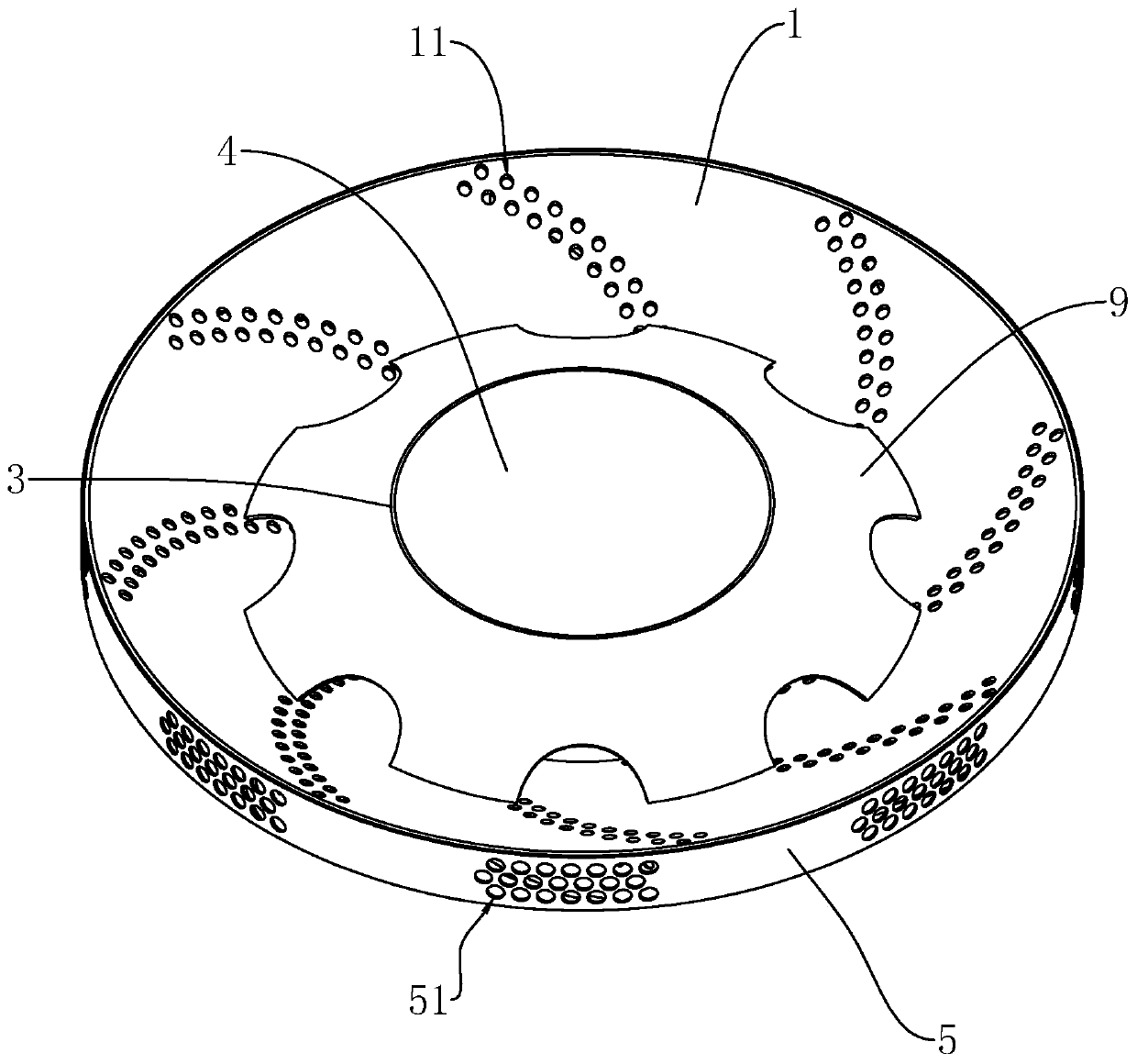
[0039] Embodiment 1: a kind of aerator impeller disclosed by the present invention, see figure 1 , comprising a roulette 1 and a straight cylinder 3 . The roulette 1 is a tapered cylinder, the straight cylinder 3 is arranged coaxially with the roulette 1, one end of the straight cylinder 3 passes through the small end of the roulette 1, and the circumferential outer wall of the straight cylinder 3 is welded to the inner diameter of the small end of the roulette 1. The other end of the straight cylinder 3 is located in the large end of the wheel disc 1, and a connecting ring 9 is provided on the circumferential outer wall of the large end of the straight cylinder 3, and the inner ring side wall of the connecting ring 9 is welded on the circumferential outer wall of the straight cylinder 3, The outer ring edge of the connecting ring 9 is welded and fixed to the side wall of the wheel disc 1 . A mounting seat 4 is fixed on the circumferential inner wall of the straight cylinder ...

Embodiment 2

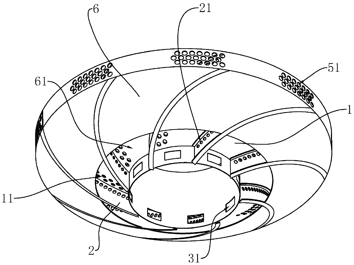
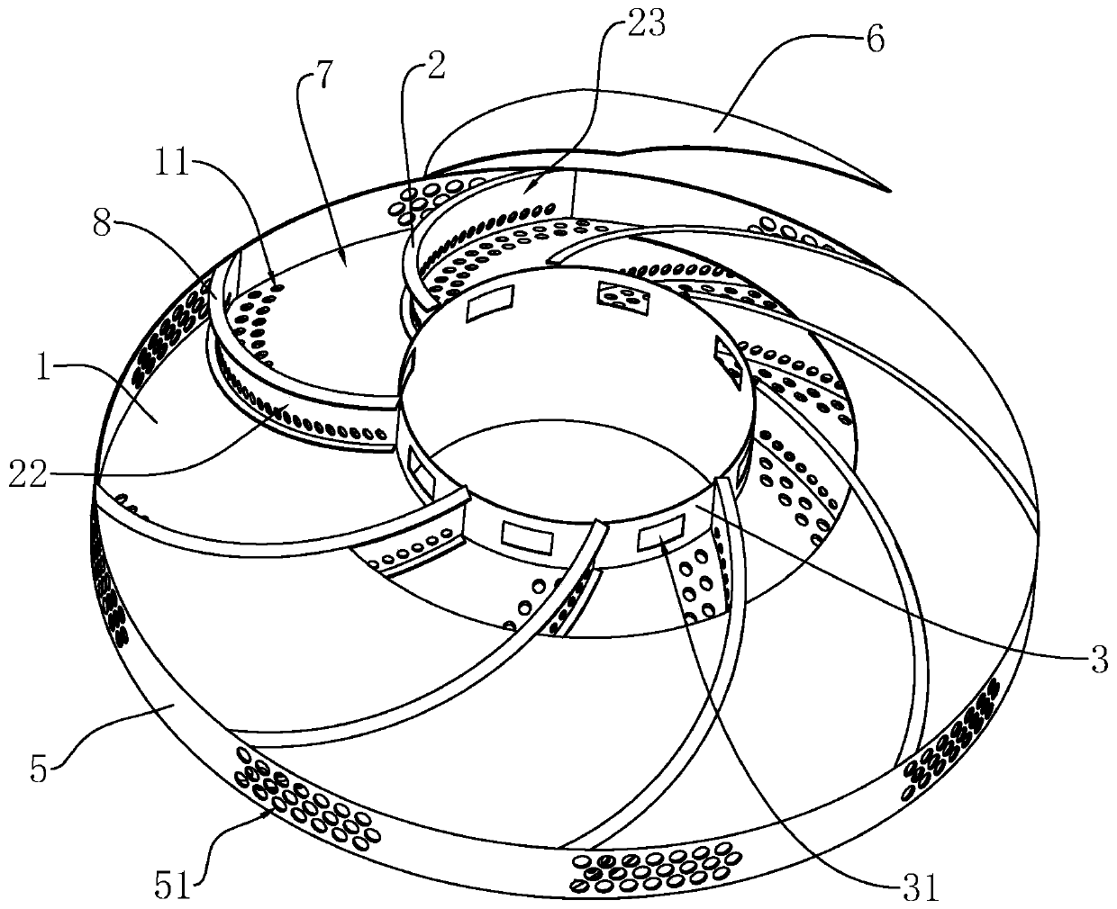
[0044] Example 2: see Figure 5 The difference between this embodiment and Embodiment 1 is that the end of the plate 6 away from the annular retaining ring 5 continues to extend along the length direction of the blade 2 and is welded to the circumferential outer wall of the straight cylinder 3 . There are multiple water inlets 61 on a plate 6, and the multiple water inlets 61 on the same plate 6 are all close to the adjacent blades 2 facing the corresponding mixing chamber 7 with the negative pressure surface 23, and the multiple water inlets 61 on the same plate 6 It is arranged along the length direction of the adjacent blade 2. Each water inlet 61 is covered with a guide piece 63, the guide piece 63 is on the side of the cover plate away from the mixing chamber 7, the shape of the guide piece 63 is a triangular cone, one side of the guide piece 63 faces the direction of rotation of the impeller and A water diversion channel communicating with the corresponding water inlet ...


PUM


Abstract

The invention relates to an impeller of an oxygen-enriching machine. The impeller comprises an impeller disc and a plurality of blades arranged on the impeller disc; a straight tube penetrating through the center of the impeller disc is fixed onto the impeller disc; the multiple blades are distributed on the outer side wall of the impeller disc in the circumferential direction of the straight tube; the impeller further comprises an annular check ring located at one side of the outer side wall of the impeller disc, and an enclosing plate; the annular check ring is arranged at the outer edge inthe circumferential direction of the impeller disc; the enclosing plate, the annular check ring and the side wall of the straight tube jointly define a cavity; the multiple blades divide the cavity into a plurality of mixing chambers; the annular check ring is provided with multiple sets of water outlets; multiple sets of air inlets are formed in the impeller disc; a plurality of water inlets areformed in the inner wall of the straight tube; and the water inlets communicate with the corresponding mixing chambers. When the impeller rotates, water continuously touches and mixes with new air entering into the mixing chambers in the process that the water flows from the water inlets to the water outlets, so that water flows is rich in air, and the mixing degree of the water and the air is improved to make oxygen enriching efficiency higher.

Description

technical field [0001] The invention relates to the technical field of aquaculture, in particular to an aerator impeller. Background technique [0002] The aeration machine is a commonly used machine in the fishery and aquaculture industry. It drives the working parts through a power source such as an electric motor or a diesel engine, so that the "oxygen" in the air is quickly transferred to the equipment in the aquaculture water body. The machine is mainly used to increase The oxygen content in the water can ensure that the fish and other organisms in the water will not be hypoxic, and at the same time, it can also inhibit the growth of anaerobic bacteria in the water and prevent the deterioration of the pool water from threatening the living environment of the island fish. [0003] At present, the Chinese patent with the notification number CN201536562U discloses an aerator impeller, including a wheel body and spokes, the spokes are fastened on the wheel body, the wheel b...

Claims


Application Information

Patent Timeline
Patent Type & Authority Applications(China)
IPC IPC(8): A01K63/04
CPCA01K63/042
Inventor 郑卫兵
Owner 郑卫兵
Why Eureka
Try Eureka