Floating head for drilling and floating drilling device

A drilling device and floating head technology, used in drilling/drilling equipment, positioning devices, transportation and packaging, etc., can solve the problems of floating reamer cutting allowance stuck, small floating amount, insufficient power, etc. Improve drilling efficiency, prevent tool jamming, and improve the effect of floating amount

Active Publication Date: 2020-06-12
上海盈为机器人有限公司
View PDF6 Cites 0 Cited by
  • Summary
  • Abstract
  • Description
  • Claims
  • Application Information

AI Technical Summary

Problems solved by technology

However, in this process, after the standard joint is positioned, when the floating rotary file device is used to remove the zinc layer or zinc tumor in the hole, the ordinary floating rotary file device has structural limitations, and the drill bit uses its own elasticity to swing when drilling. , the floating amount is small, and the efficiency of removing zinc tumors is too low. If a long-edged rotary file is selected, and there is a phenomenon of knife jamming caused by insufficient power, the floating amount is too small when drilling, so it is often due to the large error of the hole distance. Cause the floating reamer to get stuck due to excessive cutting allowance
In addition, the floating reamer is expensive, and the production cycle cannot meet customer requirements even if the tool does not jam

Method used


Image

  • Floating head for drilling and floating drilling device
  • Floating head for drilling and floating drilling device
  • Floating head for drilling and floating drilling device

Examples


Embodiment Construction

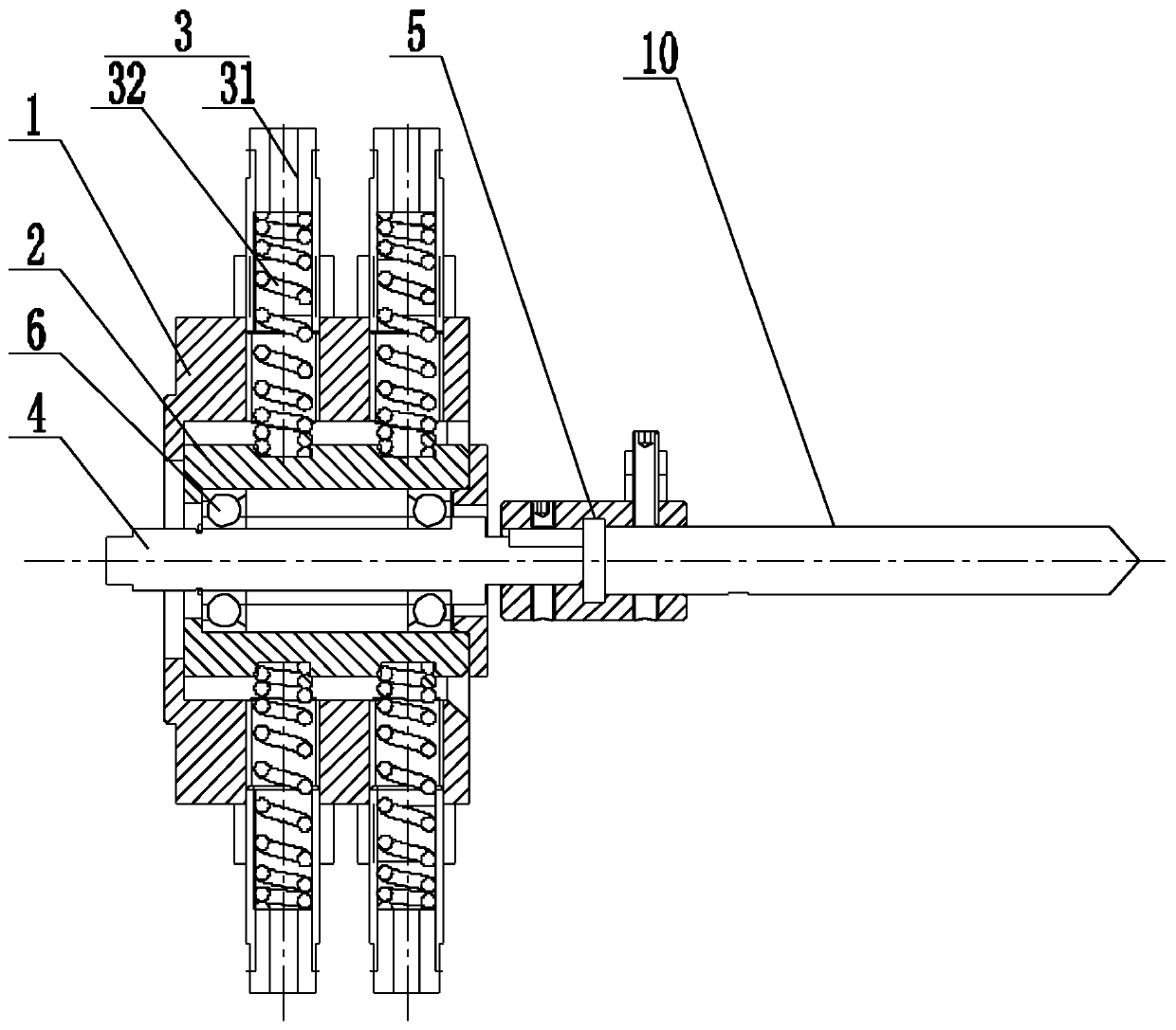
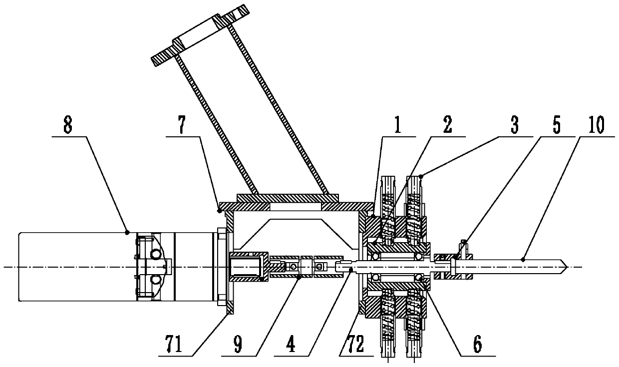
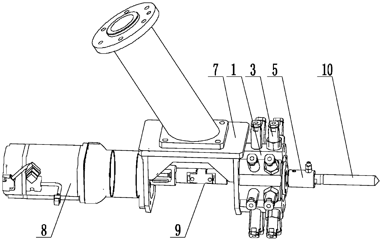
[0024] like Figures 1 to 3 as shown, figure 1 A structural schematic diagram of a floating head for drilling proposed by the present invention, figure 2 It is a structural schematic diagram of a floating drilling device proposed by the present invention, image 3 It is a schematic diagram of a three-dimensional structure of a floating drilling device proposed by the present invention.

[0025] refer to figure 1 , a floating head for drilling and a floating drilling device proposed by the present invention, comprising: an outer casing 1, a bearing seat 2, a floating connector 3, and a connecting shaft 4;

[0026] The middle part of the bearing seat 2 is provided with an installation through cavity, and a rotating bearing 6 is arranged inside the installation through cavity, and the connecting shaft 4 is arranged through the installation through cavity and is rotatably installed on the bearing seat 2 through the rotating bearing 6, and one end of the connecting shaft 4 Equ...


PUM


Abstract

The invention discloses a floating head for drilling and a floating drilling device. An installing through cavity is formed in the middle portion of a bearing pedestal. A rotating bearing is arrangedin the installing through cavity. A connecting shaft is arranged in the manner of penetrating through the installing through cavity, and installed on the bearing pedestal in a rotating manner throughthe rotating bearing. A drill bit installing station is arranged at one end of the connecting shaft. An outer sleeve is arranged on the exterior of the bearing pedestal in a sleeving manner, and a preset floating gap is spaced between the inner wall of the outer sleeve and the inner wall of the bearing pedestal. The outer sleeve and the bearing pedestal are connected through a floating connectingpart. By means of the floating head for drilling, due to optimal design, the floating gap is arranged between the outer sleeve and the bearing pedestal, the outer sleeve and the bearing pedestal are connected in a cooperating manner through the floating connecting part, the connecting shaft is installed on the bearing pedestal in a rotating manner through the bearing, in the drilling process, thedrill bit rotates along with the connecting shaft, and floats in the periphery direction of the interior of the outer sleeve along with the bearing pedestal at the same time, the floating amount of the drill bit is increased greatly, the drilling efficiency is improved, and the phenomenon that due to insufficient power, a cutter gets stuck is effectively prevented. The invention further disclosesa floating drilling device.

Description

technical field [0001] The invention relates to the technical field of drilling, in particular to a floating head for drilling and a floating drilling device. Background technique [0002] The standard section of the elevator in the engineering equipment is in the automatic production line. Since the holes on the standard section are welded after processing the holes, there is an error of about 4mm between the hole spacing on the frame and the theoretical hole spacing. Therefore, in the standard section After welding, it is necessary to carry out the process of eliminating the zinc layer in the hole. However, in this process, after the standard joint is positioned, when the floating rotary file device is used to remove the zinc layer or zinc tumor in the hole, the ordinary floating rotary file device has structural limitations, and the drill bit uses its own elasticity to swing when drilling. , the floating amount is small, and the efficiency of removing zinc tumors is too ...

Claims


Application Information

Patent Timeline
Patent Type & Authority Applications(China)
IPC IPC(8): B23B47/00B23B51/00B23Q3/00
CPCB23B51/00B23B47/00B23Q3/00
Inventor 张新伍易为程齐军刘昆
Owner 上海盈为机器人有限公司
Why Eureka
Try Eureka