
Semi-slotted hole tube type urea mixing device

A technology of mixing device and slot hole, applied in the direction of muffler device, exhaust device, exhaust gas treatment, etc., can solve the problems of difficult to complete urea decomposition quickly, difficult to ensure the uniformity of NH3 distribution, limited urea crushing ability, etc. The risk of urea crystallization, reducing pressure loss, ensuring efficiency and the effect of

Pending Publication Date: 2020-06-12
WUXI WEIFU LIDA CATALYTIC CONVERTER +1
View PDF0 Cites 3 Cited by
  • Summary
  • Abstract
  • Description
  • Claims
  • Application Information

AI Technical Summary

Problems solved by technology

In recent years, the problem of crushing and crystallization of urea has also been achieved by using a swirl structure. However, when the swirl structure is applied to U-shaped post-treatment, the direction of the swirling airflow is perpendicular to the direction of the airflow in the SCR catalyst, so it is difficult to ensure that NH3 is in the SCR. Uniformity of catalyst end face distribution
At the same time, due to the limited ability of the cyclone structure to crush urea, it is difficult to quickly decompose urea.

Method used


Image

  • Semi-slotted hole tube type urea mixing device
  • Semi-slotted hole tube type urea mixing device
  • Semi-slotted hole tube type urea mixing device

Examples


Embodiment Construction

[0027] The present invention will be further described below in conjunction with specific examples.

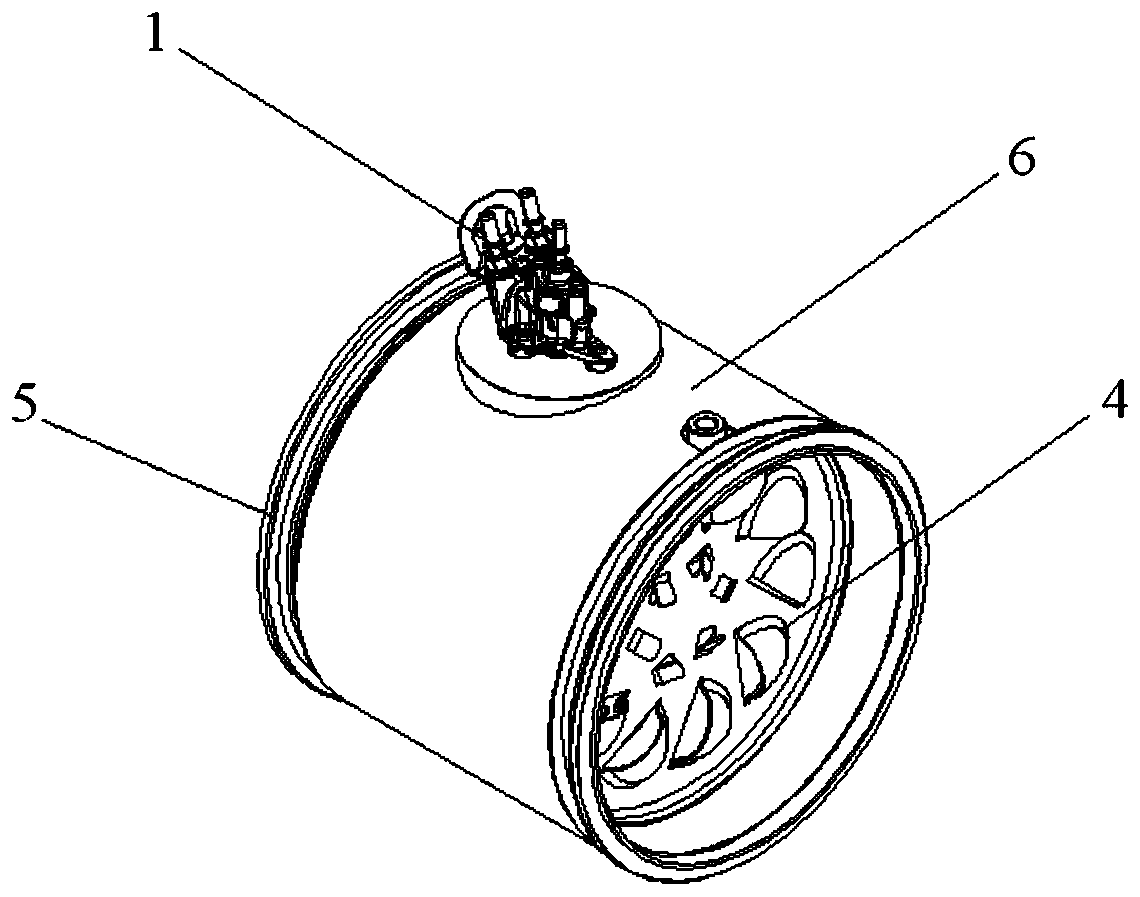
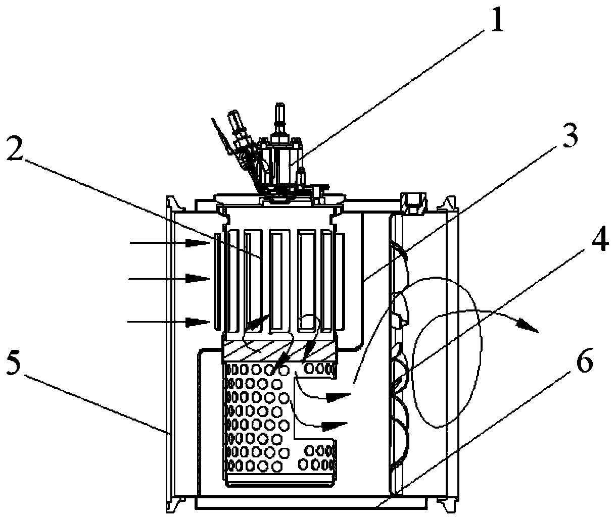
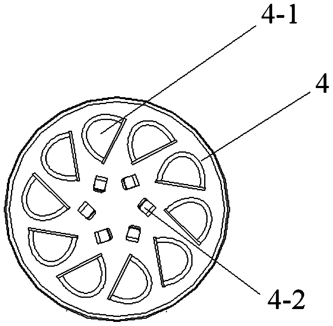
[0028] A half-slot tubular urea mixing device, such as Figure 1-7 As shown, it includes urea nozzle 1, swirl tube assembly 2, Z-shaped partition 3, swirl plate 4, inner cylinder assembly 5 and outer cylinder assembly 6;

[0029] Among them, the urea nozzle is installed on the outer cylinder assembly 6, and the swirl tube assembly 2 is inserted into the opening on the Z-shaped partition 3 and welded, and then inserted into the inner cylinder assembly 5 together with the swirl plate 4, and the outer cylinder assembly 6 is used as a heat insulation component to be sleeved on the outside of the inner cylinder assembly 5, and the urea nozzle 1 is arranged at the upper end of the outer cylinder assembly 6.

[0030] The swirl tube assembly 2 includes four parts: a swirl tube 2-1, a wire mesh ring 2-2, a half-slotted tube 2-3 and a plug cover 2-4, wherein a swirl is welded above the...


PUM


Abstract

The invention relates to a semi-slotted hole tube type urea mixing device. The semi-slotted hole tube type urea mixing device comprises a urea nozzle, a cyclone tube assembly, a Z-shaped partition plate, a cyclone plate, an inner cylinder assembly and an outer cylinder assembly, wherein the urea nozzle is mounted on the outer cylinder assembly, the cyclone tube assembly is inserted into a hole inthe Z-shaped partition plate and welded, then the cyclone tube assembly and the cyclone plate are plugged into the inner cylinder assembly together, the outer cylinder assembly is taken as a heat insulation part and arranged on the outer side of the inner cylinder assembly in a sleeving manner, and the urea nozzle is arranged at the upper end of the outer cylinder assembly. The mixing device can realize mixing of urea and airflow and improve the distribution uniformity of ammonia gas on the end surface of an SCR carrier.

Description

technical field [0001] The invention belongs to the technical field of urea mixing devices, in particular to a half-slot tube type urea mixing device. Background technique [0002] In the SCR system application technology, how to uniformly mix the injected urea and engine exhaust gas and complete the secondary crushing of urea and reduce the risk of crystallization of urea at the mixer position is the key to the entire development process. The U-shaped post-processor is a key component of the commercial vehicle post-treatment system in the National VI emission stage, and its urea mixing device is still immature. [0003] Common mixing units mostly use fin structures or fiber units to achieve crushing. Due to the difficulty of micro-fin processing and other problems, the fin structure mostly adopts a large fin structure, and the crushing effect on urea is limited. In recent years, the problem of crushing and crystallizing urea has also been achieved by using a swirl structu...

Claims


Application Information

Patent Timeline
Patent Type & Authority Applications(China)
IPC IPC(8): F01N3/28F01N3/20F01N13/14
CPCF01N3/2892F01N3/2066F01N13/14F01N2610/02F01N2610/1453
Inventor 陈增响何龙张旭何伟娇马相雪付细平蒋海荣王述超
Owner WUXI WEIFU LIDA CATALYTIC CONVERTER
Learn More