Band-pass filter based on fan-shaped microstrip resonant cavity

A band-pass filter and microstrip resonance technology, applied in waveguide-type devices, electrical components, circuits, etc., can solve the problem of large filter insertion loss, achieve good stop-band characteristics, good out-of-band suppression characteristics, and parameter adjustment. easy effect

Active Publication Date: 2020-06-12
UNIV OF ELECTRONICS SCI & TECH OF CHINA
View PDF8 Cites 0 Cited by
  • Summary
  • Abstract
  • Description
  • Claims
  • Application Information

AI Technical Summary

Problems solved by technology

Although this technology realizes the miniaturization design of the filter, the shortcoming of this method is obvious, because the characteristics of the slow wave structure itself cause the insertion loss of the filter to be large (A.Ebrahimi, W.Withayachumnankul, S.F.Al-Sarawi andD. Abbott, "Compact Second-Order Bandstop Filter Based on Dual-Mode Complementary Split-Ring Resonator", Microwave and Wireless Components Letters, IEEE, vol.26, pp.571-573, 2016)

Method used


Image

  • Band-pass filter based on fan-shaped microstrip resonant cavity
  • Band-pass filter based on fan-shaped microstrip resonant cavity
  • Band-pass filter based on fan-shaped microstrip resonant cavity

Examples


Embodiment 1

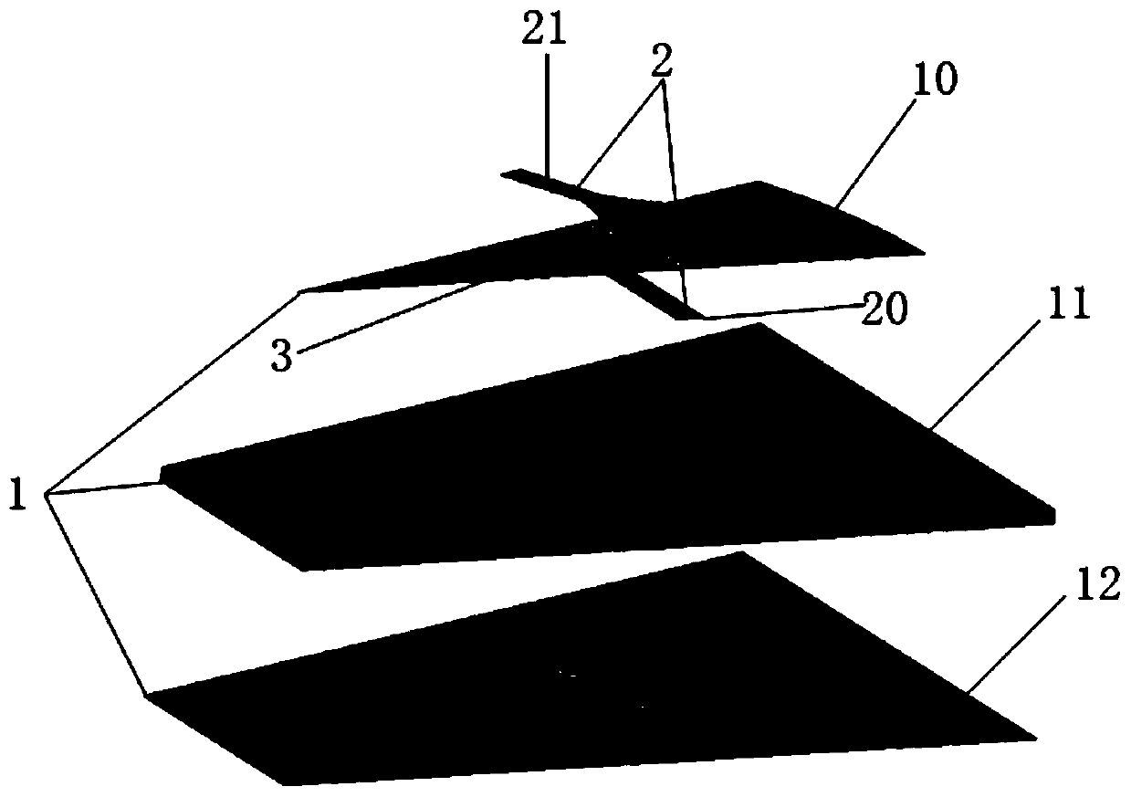
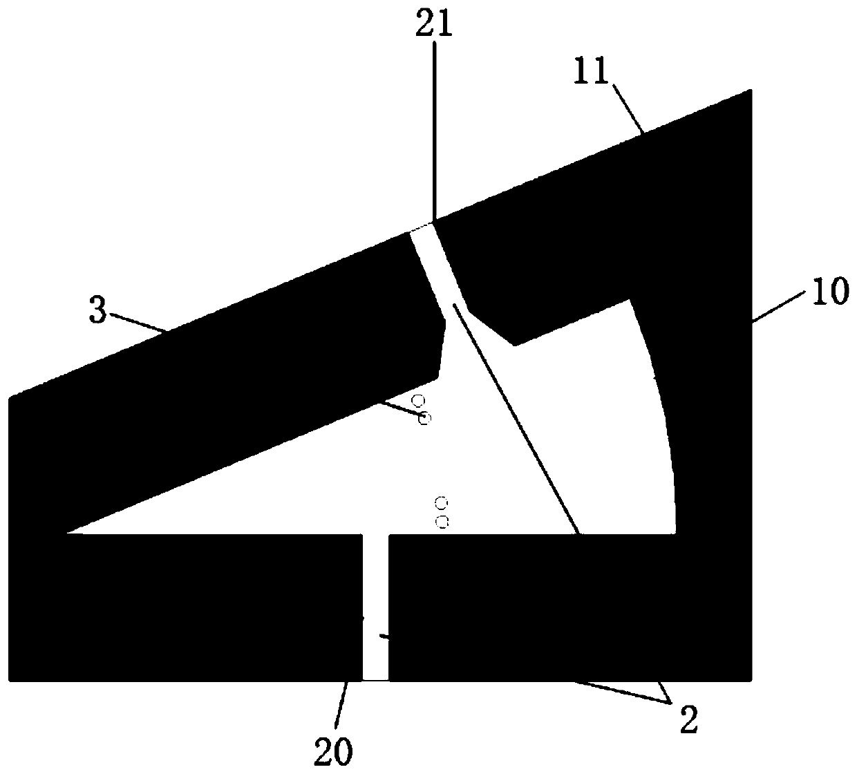
[0020] figure 1 It is a schematic diagram of the overall structure of a specific embodiment of the present invention, including a fan-shaped microstrip resonator 1 , input and output feeders 2 and metallized through holes 3 . The fan-shaped microstrip resonator 1 is sequentially formed by stacking the top fan-shaped metal patch 10, the single-layer dielectric substrate 11 of the middle layer and the bottom metal patch 12 from top to bottom. The radius of the top fan-shaped metal patch 10 It is 27mm, the radian is 22.5°, the thickness is 0.017mm, and the size is equivalent to one sixteenth of the circular metal patch with the same radius. The single-layer dielectric substrate 11 of the middle layer is a low-loss TaconicRF-35 with a thickness of 0.508 mm. It is in the shape of a right-angled trapezoid, with an upper base length of 11.46 mm, a lower base length of 23.92 mm, and a height of 30.1 mm. The size of the bottom metal patch 12 is the same as that of the single-layer die...

Embodiment 2

[0024]In this embodiment, the shapes of the single-layer dielectric substrate 11 and the bottom metal patch 12 of the middle layer are changed from a right-angled trapezoid to any other shape at the same time, while ensuring the shape of the single-layer dielectric substrate 11 of the middle layer and the bottom metal patch 12 The same size and its outer frame size needs to exceed the outer frame size of the fan-shaped metal patch 10 on the top layer plus the input and output feeder 2, and the input and output feeder ports need to be in the outer outline of the single-layer dielectric substrate 11 and the bottom metal patch 12 in the middle layer Online, other parts are completely the same as those in Embodiment 1, and the functions of the present invention can still be realized.

Embodiment 3

[0026] In this embodiment, the transmission line structure of the input and output feeder 2 is changed from a gradual transmission line to a step impedance transmission line structure, and other parts are completely the same as in the first embodiment, and the functions of the present invention can still be realized.


PUM


Abstract

The invention discloses a band-pass filter based on a fan-shaped microstrip resonant cavity. The filter comprises a fan-shaped microstrip resonant cavity, an input and output feeder line and a metallized through hole, the metalized through hole is used as a disturbance structure to enable the resonant frequencies of the first two resonant modes of the resonant cavity to be close to form a passband, and meanwhile, a transmission zero point is introduced into a stop band by utilizing a signal phase theory under the condition of not changing the size and the structure of the original resonant cavity, so that a better out-of-band rejection characteristic is realized. The filter can be used for microwave and millimeter wave communication and occasions with high requirements for out-of-band rejection performance in a radar system. Meanwhile, the band-pass filter has the advantages of miniaturization, light weight, easiness in integration and low cost, and can better adapt to the requirementsof modern communication and radar systems.

Description

technical field [0001] The invention belongs to the technical field of microwave and millimeter wave filters, and relates to a microstrip filter. Background technique [0002] With the rapid development of modern microwave and millimeter wave circuit systems, the system puts forward more complex functional requirements and higher electrical performance indicators for each component. In earlier microwave and millimeter wave circuit systems, most transmission lines and passive circuit structures were made based on metal waveguides. This structure has the advantages of high Q value, low loss, and high power capacity, but processing and debugging are relatively difficult. Therefore, in order to meet the miniaturization and integration requirements of modern microwave and millimeter wave circuit systems, planar integrated transmission lines have emerged, and the microstrip line structure has received high attention and extensive research. Compared with metal waveguide transmissi...

Claims


Application Information

Patent Timeline
Patent Type & Authority Applications(China)
IPC IPC(8): H01P1/207
CPCH01P1/207
Inventor 张永鸿刘家玮伯晓乐敬怀舒屈丽丽樊勇
Owner UNIV OF ELECTRONICS SCI & TECH OF CHINA
Why Eureka
Try Eureka