A low-carbon control method for power systems containing gas-coal-fired-wind turbines

A technology of wind turbines and power systems, applied in the field of power systems, can solve the problems of less research on low-carbon operation strategies of power systems, and achieve the effects of improving wind power utilization, promoting wind power consumption, and reducing the cost of carbon emissions on the load side

Active Publication Date: 2022-05-27
NORTHEAST DIANLI UNIVERSITY
View PDF5 Cites 0 Cited by
  • Summary
  • Abstract
  • Description
  • Claims
  • Application Information

AI Technical Summary

Problems solved by technology

However, there are few studies on the low-carbon operation strategy of the power system with the participation of the load side.

Method used


Image

  • A low-carbon control method for power systems containing gas-coal-fired-wind turbines
  • A low-carbon control method for power systems containing gas-coal-fired-wind turbines
  • A low-carbon control method for power systems containing gas-coal-fired-wind turbines

Examples


Embodiment 1

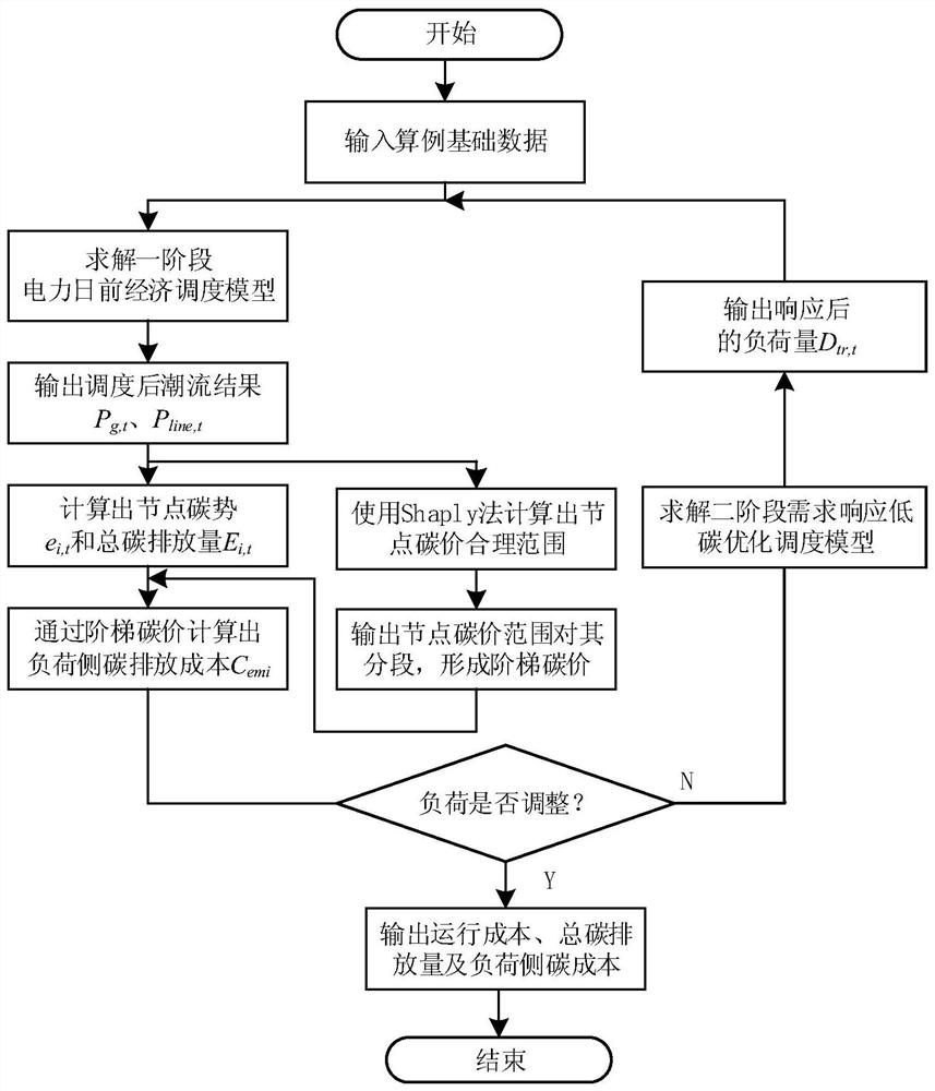
[0051]The embodiment of the present invention establishes a low-carbon control method for a power system including gas-coal-fired-wind turbines, transfers the responsibility of carbon emissions from the power generation side to the load side for accounting, and flexibly adjusts the load during dispatching through the demand response capability of the load side The distribution within the cycle can effectively reduce the total carbon emissions of the system and the cost of carbon emissions on the load side, and provide a more feasible reference for the power control method under the low-carbon background, including the following steps:

[0052] 101: Based on the carbon emission flow theory, assign the carbon emission responsibility of the power generation side to the load side, and calculate the carbon potential and total carbon emission of each node on the load side when there is no response;

[0053] 102: Introduce the Shapley value to share the responsibility of carbon emissi...

Embodiment 2

[0059] Combine below figure 1 , Table 1 and the specific calculation formula are further introduced to the scheme in Example 1, see the description for details:

[0060] 201: An overview of the theory of carbon emission flow in the power system:

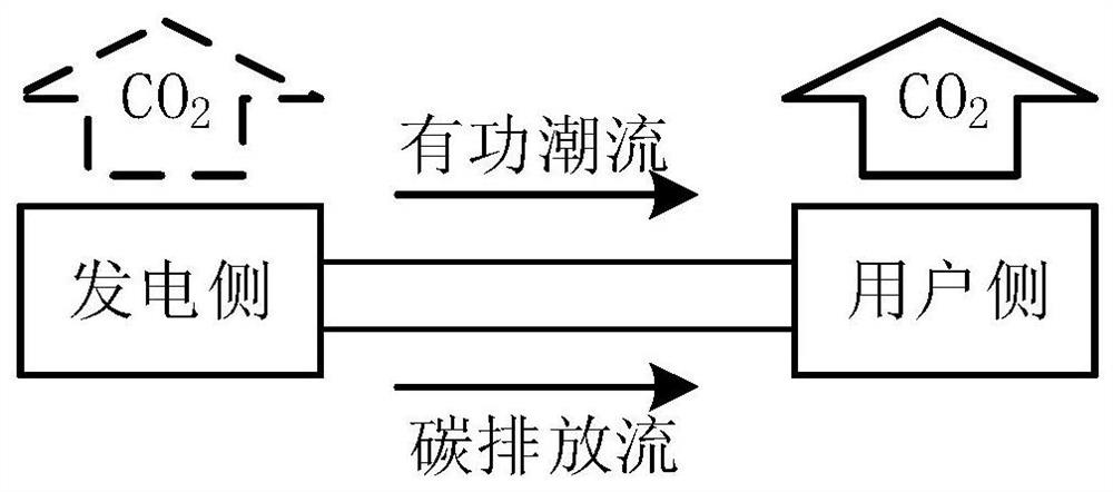
[0061] When fossil fuels are used to generate electricity, a large amount of carbon dioxide is produced after combustion, resulting in carbon emissions. Due to the dependence between carbon emissions and currents, such as figure 1 As shown, carbon emission data labels can be added to the power flow data to form the basis of the carbon emission flow theory.

[0062] The theoretical concepts and indicators of carbon emission flow in the power system are shown in Table 1:

[0063] Table 1 Basic concepts and indicators of carbon emission theory

[0064]

[0065] According to the principle of proportional sharing, any branch of the outgoing power flow has a component of each incoming power flow, let N + and N - is the set of bran...

Embodiment 3

[0145] The following is a combination of specific examples, Figure 3-8 , and table 1-6 carry out feasibility verification to the scheme in embodiment 1 and 2, see below for details:

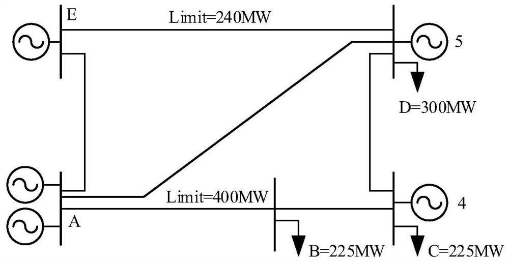
[0146] 301: PJM-5 Node Test System

[0147] Table 1 Unit parameters

[0148]

[0149]

[0150] This example takes the PJM-5 node system as an example for analysis and verification. image 3 Take the PJM-5 node system as an example for analysis. The system includes 5 generator nodes, 6 transmission lines and 3 load nodes B, C, and D. The specific system parameters are shown in Table 1.

[0151] Figure 4 Predict the total load and forecast wind power output for the system within 24 hours. The predicted hourly total load is evenly distributed to load nodes B, C, and D, and the load value of each node in each period is obtained. Establish a two-stage low-carbon economic dispatch model for the PJM-5 node full thermal power scenario and the scenario with wind turbines, and calculate the re...


PUM


Abstract

The invention discloses a low-carbon control method for a power system including gas-coal-fired-wind turbines. The method includes: based on the theory of carbon emission flow, assigning the carbon emission responsibility of the power generation side to the load side, and calculating the non-response time The carbon potential and total carbon emissions of each node on the load side; the Shapley value is introduced to share the carbon emission responsibility to calculate the reasonable range of carbon emissions of each load node, and then according to the reasonable range of carbon emissions and the step-by-step carbon price formulation, the nodes on the load side when there is no response are calculated The cost of carbon emissions; build a two-stage optimization model based on the economic dispatch of the power system as a first-stage optimization model and demand response low-carbon optimal dispatch with carbon prices as a signal, and adjust the load on the user side through demand response, and calculate the load after the response The total carbon emissions and carbon emission costs of each node on the side are compared with the data before the response, thereby reducing the total carbon emissions and carbon emission costs. The invention utilizes the load-side regulation ability to reduce system carbon emission.

Description

technical field [0001] The invention relates to the field of power systems, in particular to a low-carbon control method for a power system containing a gas-coal-fired-wind generator set. Background technique [0002] Global warming caused by excessive consumption of fossil fuels is one of the most severe challenges facing the survival and development of human society. The role of CO2 in the warming effect caused by greenhouse gases is as high as 77% [1-2] . As one of the main sources of carbon emissions, the low-carbon development of the power industry has become an important task, and striving to achieve low-carbon development is a new theme for the development of the power industry under the new situation [3] . [0003] At present, the primary energy used in power production is still dominated by fossil energy such as coal, resulting in huge carbon emissions. Since carbon emissions and power generation are closely related, in the traditional sense, the research on car...

Claims


Application Information

Patent Timeline
Patent Type & Authority Patents(China)
IPC IPC(8): H02J3/46
CPCH02J3/46Y02E10/76
Inventor 陈厚合张儒峰茅文玲姜涛李雪李国庆王长江李本新李曙光
Owner NORTHEAST DIANLI UNIVERSITY
Why Eureka
Try Eureka