Electrolytic capacitor module, filter circuit and power converter

A technology of electrolytic capacitors and power converters, which is applied in the direction of electrolytic capacitors, capacitor electrodes, capacitors, etc., can solve the problems of large loss of aluminum electrolytic capacitors, etc., and achieve the effects of simplifying cooling components, improving ripple current tolerance, and reducing the rate of capacitance.

Active Publication Date: 2020-06-12
NIPPON CHIMI CON CORP
View PDF16 Cites 0 Cited by
  • Summary
  • Abstract
  • Description
  • Claims
  • Application Information

AI Technical Summary

Problems solved by technology

However, this patent document 1 only describes that the loss of aluminum electrolytic capacitors is large, and does not mention the use of electrolytic capacitors in the parallel connection of capacitors described in patent document 1.

Method used


Image

  • Electrolytic capacitor module, filter circuit and power converter
  • Electrolytic capacitor module, filter circuit and power converter
  • Electrolytic capacitor module, filter circuit and power converter

Examples


Embodiment approach

[0068]

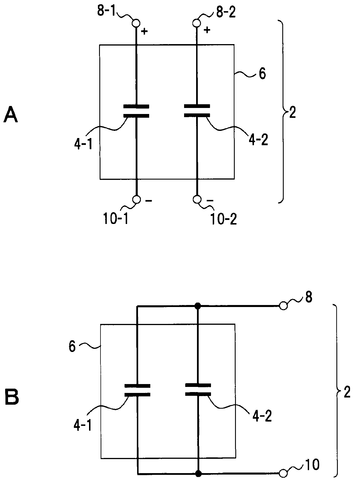
[0069] figure 1 A shows an embodiment of an electrolytic capacitor module. figure 1 The configuration shown is an example and is not limited to the configuration described above.

[0070] This electrolytic capacitor module (hereinafter simply referred to as “capacitor module”) 2 includes at least two electrolytic capacitors in which electrode foils have etching pits formed therein. These electrolytic capacitors are a first electrolytic capacitor 4-1 and a second electrolytic capacitor 4-2 as two types of electrolytic capacitors having different etch pit lengths. Here, regarding the "two types of different etching pit lengths", the length (depth) of the tunnel-shaped etching pit formed in the electrode foil of the capacitor element used in the electrolytic capacitor is called the pit length, and the pit length is used as a classification concept Classified.

[0071] In this one embodiment, the electrolytic capacitor 4 - 1 shows the case of an electrolytic capacito...

Embodiment 1~ Embodiment 4 and comparative example 1~ comparative example 4

[0194] Hereinafter, Examples 1 to 4 and Comparative Examples 1 to 4 will be described. Figure 12 The pit length, the frequency, and the electrostatic capacitance as the measurement results of the first to third times, and their average values ​​are shown.

Embodiment 1

[0196] The capacitor element of Example 1 in which the anode foil used the electrode foil whose etching pit length=27 [μm] was manufactured.

[0197] As the electrode foil on the anode side, an aluminum foil having a size of 20 [mm]×20 [mm] and a foil thickness of 125 [μm] was used as the anode foil. The electrode foil was subjected to two-stage etching treatment. In the first-stage etching treatment, the electrode foil was dipped in an aqueous solution containing hydrochloric acid, and the aluminum foil was electrochemically etched with DC voltage to form etching pits.

[0198] In the second-stage etching treatment, the electrode foil subjected to the first-stage etching treatment is immersed in an aqueous solution containing nitric acid, and the etching treatment is performed electrochemically or chemically to expand the etching pits formed in the first-stage. The electrode foil subjected to such etching treatment was subjected to a chemical conversion treatment in an ammoni...


PUM

PropertyMeasurementUnit
lengthaaaaaaaaaa
lengthaaaaaaaaaa
capacitanceaaaaaaaaaa

Abstract

This electrolytic capacitor module is provided with at least two electrolytic capacitors (4-1, 4-2) having etch pits formed on an electrode foil. At least two types of electrolytic capacitors (4-1, 4-2) with different etch pit lengths are connected in parallel, and the number installed thereof may be the same or different. The electrolytic capacitors (4-1, 4-2) are either electrolytic capacitors with etch pit lengths less than or equal to 27 [mu]m, or electrolytic capacitors with etch pit lengths greater than 27 [mu]m. By this means, performance in the high-frequency region of the electrolyticcapacitor is improved, the capacity reduction rate in the high-frequency region is suppressed, and the ripple current resistance in the high-frequency region is increased.

Description

technical field [0001] The technique of the invention concerns the modularization and circuit technology of electrolytic capacitors specified by electrode foils with different etch pit lengths. Background technique [0002] For DC and AC power conversion, a power converter that performs power conversion by switching, such as an inverter or a converter, is used. In this power converter, a filter including a capacitor is used to remove high-frequency components generated during switching. [0003] As for capacitors used in this filter, it is known to use a large-capacity capacitor having a large high-frequency loss and a small-capacity capacitor having a small high-frequency loss in parallel (Patent Document 1). However, this patent document 1 only describes that the loss of an aluminum electrolytic capacitor is large, and does not mention the use of an electrolytic capacitor for the parallel connection of capacitors described in patent document 1. [0004] prior art literat...

Claims


Application Information

Patent Timeline
Patent Type & Authority Applications(China)
IPC IPC(8): H01G9/055H01G4/40H01G9/28H02M1/14
CPCH02M1/14H01G4/40H01G9/04H01G9/055H01G9/28H01G9/26H02M7/5387H02P27/06
Inventor 吉田敦
Owner NIPPON CHIMI CON CORP
Why Eureka
Try Eureka