Automatic collecting device for combustion waste gas generation area and provided with swing rod

A technology for automatic collection of combustion exhaust gas, applied in auxiliary devices, gas treatment, smoke and dust removal, etc., can solve problems such as unusable, high cost, and difficult to move, and achieve the effects of easy portability, cost saving, and simple structure

Active Publication Date: 2020-06-16
嘉兴量创科技有限公司
View PDF9 Cites 2 Cited by
  • Summary
  • Abstract
  • Description
  • Claims
  • Application Information

AI Technical Summary

Problems solved by technology

[0006] In order to solve the above-mentioned technical problems, the present invention provides an automatic collection device for the combustion waste gas generation area equipped with a swing rod, so as to solve the problem that the waste gas collection device is relatively large overall and difficult to move, and cannot be used when welding pipes in outdoor trenches. Moreover, the problem of high overall cost

Method used


Image

  • Automatic collecting device for combustion waste gas generation area and provided with swing rod
  • Automatic collecting device for combustion waste gas generation area and provided with swing rod
  • Automatic collecting device for combustion waste gas generation area and provided with swing rod

Examples


Embodiment

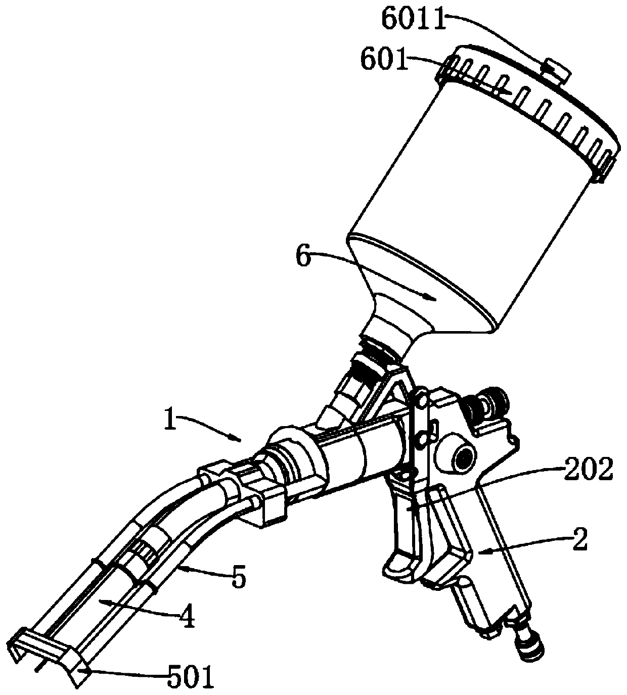
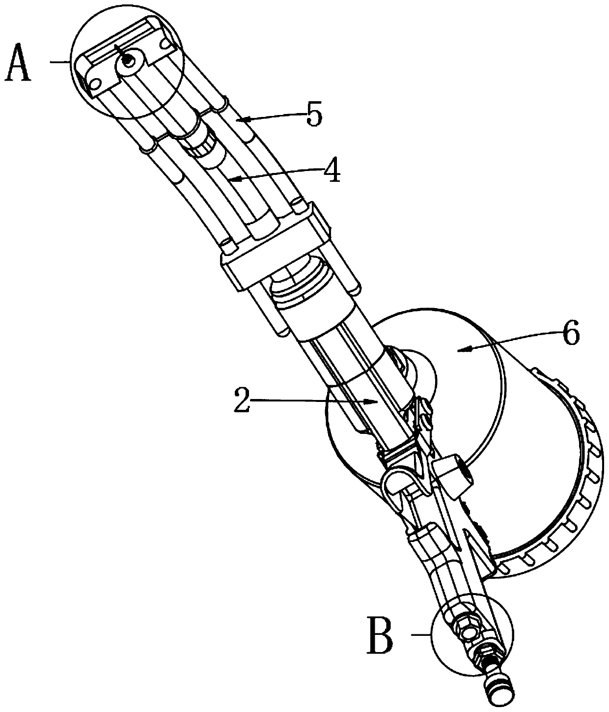
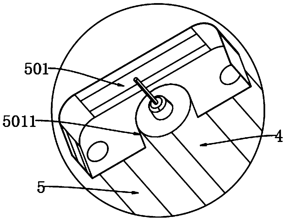
[0034] as attached figure 1 to attach Figure 9 Shown:

[0035] The present invention provides an automatic collection device for a combustion waste gas generation area equipped with a swing rod, which includes a device main body 1; One end of the bottom side of the handle body 2 is provided with an argon gas inlet connection port 201, and the inner side of the argon gas inlet connection port 201 is provided with an internal thread and is tightly connected with the argon delivery pipe 2036. The front end is provided with a separation chamber 203, and the welding torch tube 4 is connected to the front end of the separation chamber 203, and the waste gas collection pipe 5 is connected to both sides of the welding torch pipe 4 through a clamp ring 502, and the rear end of the waste gas collection pipe 5 passes through Into the separation chamber 203, the lower end of the filter cartridge 6 is connected to the exhaust gas outlet connection port 2035 by thread sealing and contact...


PUM


Abstract

The invention provides an automatic collecting device for a combustion waste gas generation area and provided with a swing rod. The device comprises a device main body; the front side end of a handheld body is provided with a separation cavity, a welding gun pipe is connected to the front end of the separation cavity, waste gas collection pipes are connected to the two sides of the welding gun pipe through clamping rings, the rear ends of the waste gas collection pipes penetrate into the separation cavity, and the lower end of a filter cylinder is hermetically connected to a waste gas outlet connection opening through threads and is in inclined contact with the upper end of the handheld body. A trigger switch is pulled to drive the swinging rod to move backwards, so that the conical frontend of a U-shaped structure of the swinging rod is respectively disconnected from a sealing vertical plate B, a left lower chamber communicates with a right lower chamber, argon in the right lower chamber can flow into the left lower chamber, the argon enters the welding gun tube through a through hole in the lower end of a sealing vertical plate A, and a right upper chamber communicates with a left upper chamber; and the exhaust gas flows through the filter cylinder and is collected in a vacuum bottle or an exhaust device by using a vacuum or an exhaust pipe connected with an external connecting pipe.

Description

technical field [0001] The invention belongs to the technical field of waste gas collection, and more specifically relates to an automatic collection device for combustion waste gas generation areas equipped with swing rods. Background technique [0002] Exhaust gas collection device refers to a set of gas collection equipment used for environmental protection treatment equipment. Its main purpose is to introduce harmful gas or dust generated by the reaction into the purification system, and at the same time prevent it from spreading to the production workshop and the atmosphere, causing pollution. [0003] For example, in the patent with the application number: CN201820758907.8, an automatic exhaust gas collection device is disclosed. The automatic exhaust gas collection device includes an exhaust gas collection cover, an exhaust pipe and a bracket, and the exhaust pipe is connected to the top of the exhaust gas collection cover. , the bracket is provided with a fixed shaft...

Claims


Application Information

Patent Timeline
Patent Type & Authority Applications(China)
IPC IPC(8): B08B15/04B01D46/24B01D46/00B01D46/30B01D53/04B23K37/00
CPCB01D46/0036B01D46/24B01D46/30B01D53/04B01D2258/02B08B15/04B23K37/00
Inventor 郝玲
Owner 嘉兴量创科技有限公司
Why Eureka
Try Eureka