Deep multistage dynamic foundation pit precipitation system and precipitation method thereof

A foundation pit and deep-layer technology, applied in the direction of infrastructure engineering, construction, etc., can solve problems such as difficult processing, increased project cost, and insufficient lap length, etc., to achieve less interference in engineering construction, ensure water-free operation, and reduce pumping The effect of head

Pending Publication Date: 2020-06-16
FUJIAN UNIV OF TECH
View PDF0 Cites 1 Cited by
  • Summary
  • Abstract
  • Description
  • Claims
  • Application Information

AI Technical Summary

Problems solved by technology

During the construction of the water-stop pile and the water-stop curtain, there are often problems such as insufficient lap joints and insufficient lap length. Replenishment of piles will also cause delays in the construction period, increase the cost of the project, and have a greater impact on the safety of the foundation pit structure and the surrounding environment

Method used


Image

  • Deep multistage dynamic foundation pit precipitation system and precipitation method thereof
  • Deep multistage dynamic foundation pit precipitation system and precipitation method thereof
  • Deep multistage dynamic foundation pit precipitation system and precipitation method thereof

Examples


Embodiment 1

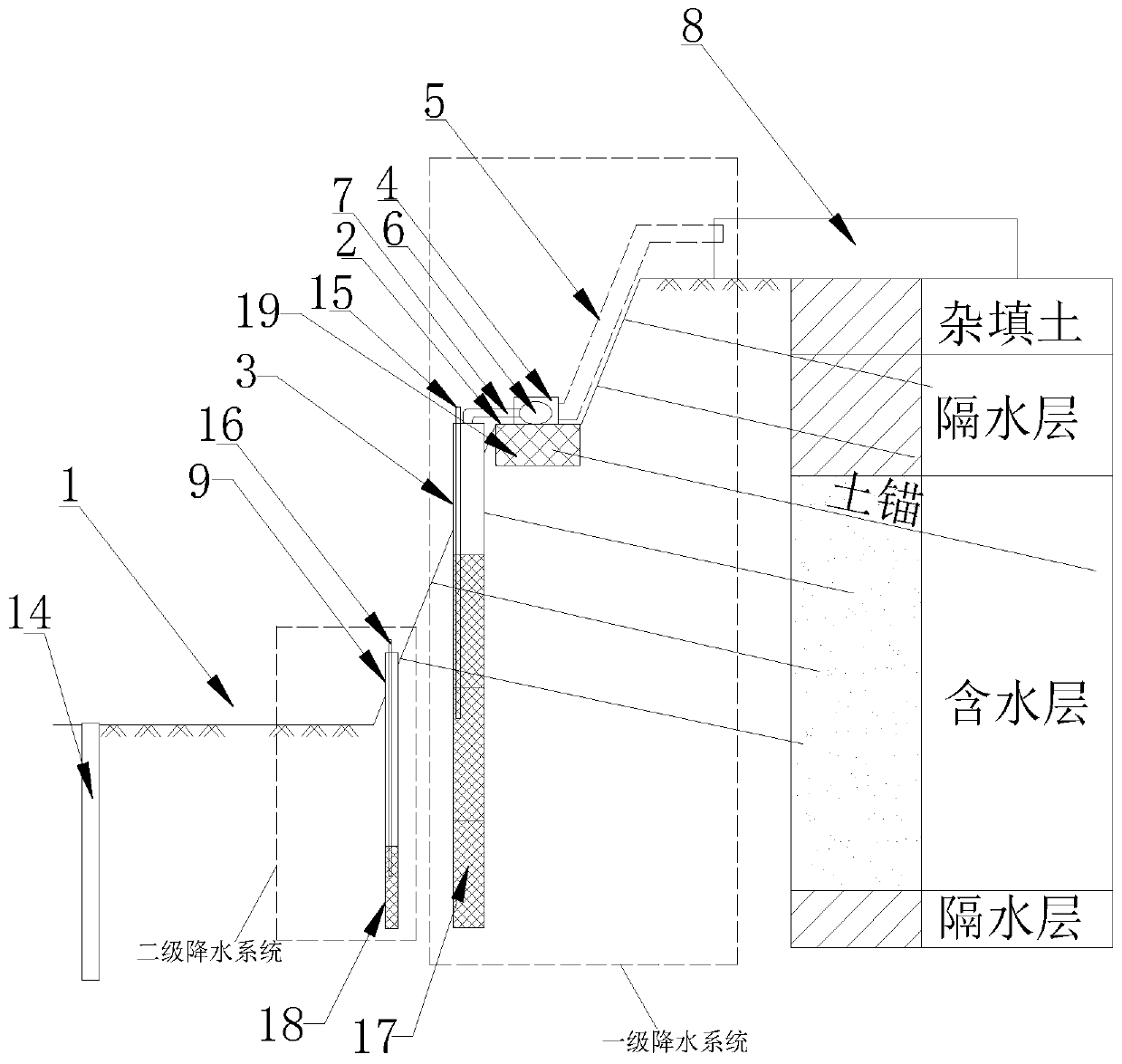
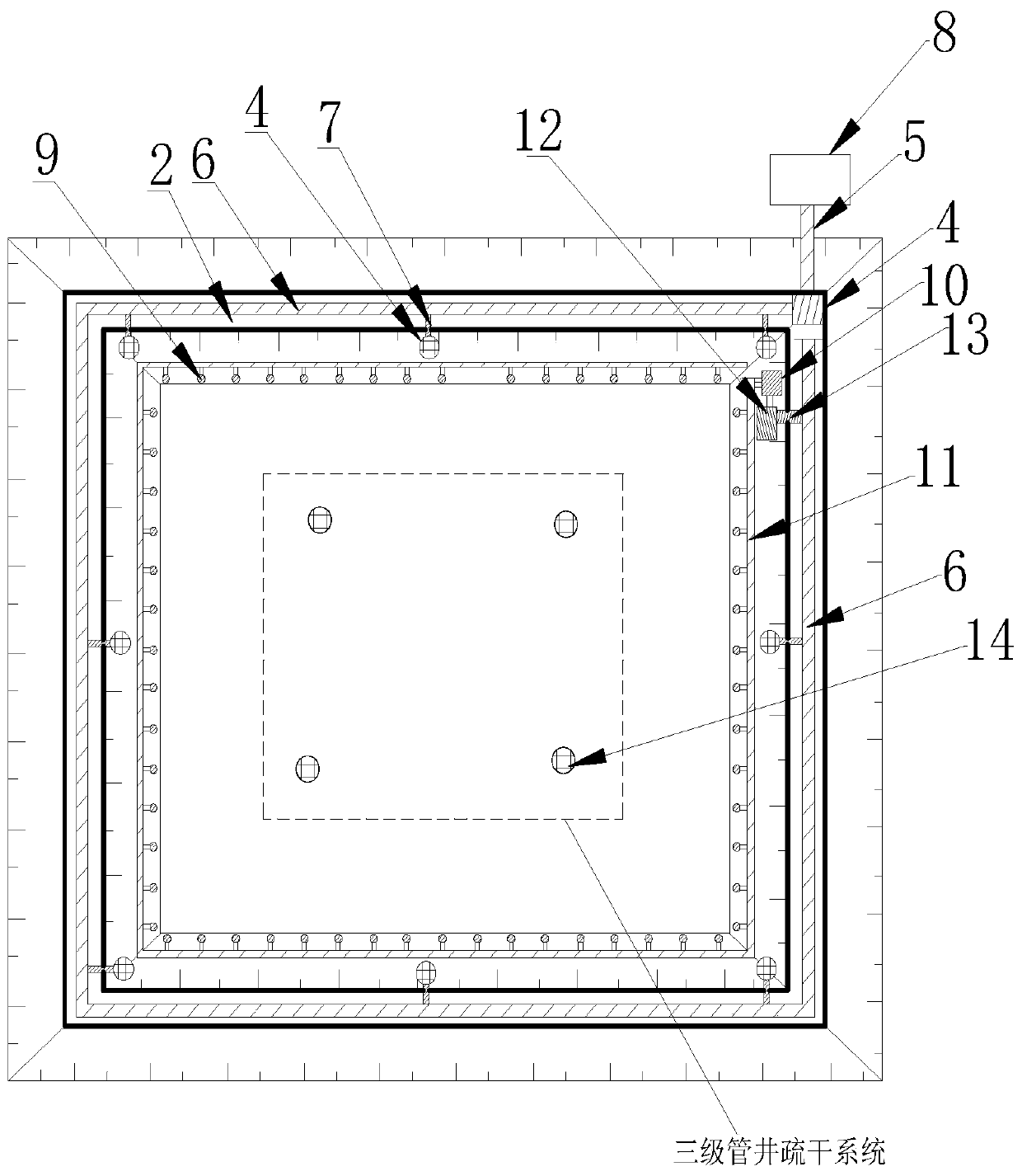
[0030] Embodiment 1: a deep multi-level dynamic foundation pit 1 dewatering system, such as figure 1 and figure 2As shown, it includes a foundation pit 1, the foundation pit 1 is excavated with steps 2, and the foundation pit 1 is provided with a plurality of dewatering pipe wells 3 at equal intervals at the toe of the grading slope. The top surface of the step 2 is provided with a booster pump 4 , a water delivery main pipe 5 and an annular drainage header 6 , and the water delivery header 5 and the annular drainage header 6 are connected to the booster pump 4 . The downpipe well 3 is connected to the annular drainage main pipe 6 through a first branch pipe 7 . The top surface of the foundation pit 1 is provided with a sedimentation tank 8 , and the water outlet end of the water delivery main pipe 5 is connected with the sedimentation tank 8 . The bottom of the foundation pit 1 is provided with a plurality of light well points 9 at equal intervals. A well point pump 10 an...

Embodiment 2

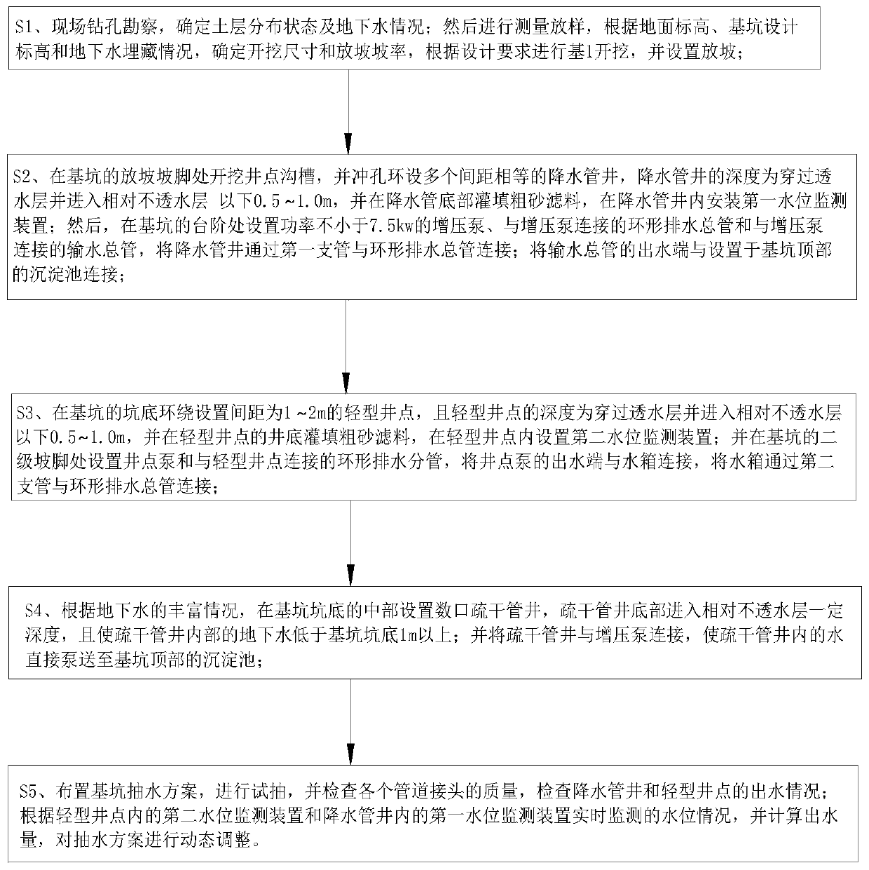
[0042] Embodiment 2: a deep multi-level dynamic foundation pit 1 dewatering method, such as image 3 shown, including the following steps:

[0043] S1. On-site drilling investigation to determine the distribution status of soil layers and groundwater conditions. Then measure and stake out, determine the excavation size and grading slope rate according to the ground elevation, the design elevation of the foundation pit 1 and the groundwater burial situation, excavate the foundation pit 1 according to the design requirements, and set the grading.

[0044] S2. Excavate well point trenches at the foot of the grading slope of foundation pit 1, and set a plurality of dewatering pipe wells 3 with equal spacing around the holes. The depth of dewatering pipe wells 3 is to pass through the permeable layer and enter below the relatively impermeable layer 0.5-1.0m, and the bottom of the downpipe is filled with coarse sand filter material 17, and a first water level monitoring device 15 i...


PUM


Abstract

The invention discloses a deep multistage dynamic foundation pit precipitation system and a precipitation method of the deep multistage dynamic foundation pit precipitation system, and relates to thetechnical field of civil engineering construction. The deep multistage dynamic foundation pit precipitation system is characterized in that the deep multistage dynamic foundation pit precipitation system comprises a foundation pit, a sedimentation tank, a booster pump, an annular drainage main pipe, a water delivery main pipe, a precipitation pipe well, a light well point, a well point pump, an annular drainage branch pipe, a water tank and a desiccation pipe well, wherein the foundation pit is provided with steps. The precipitation pipe well is connected with the annular drainage main pipe through a first branch pipe to form a one-stage pipe well precipitation system. The water tank is connected with the annular drainage main pipe through a second branch pipe to form a secondary light well point precipitation system. The desiccation pipe well and the booster pump form a three-stage pipe well desiccation system. According to the precipitation system, an open deep multistage precipitation mode is formed by a primary precipitation system and a secondary precipitation system, the pipe well pumping lift can be reduced, and drainage flow is greatly increased. Due to the combination withthe three-stage pipe well desiccation system, the drainage efficiency is improved, and the water-free operation of the foundation pit is ensured. A drainage and desiccation system has little interference on engineering construction, is low in engineering cost and has strong applicability.

Description

technical field [0001] The invention relates to the technical field of civil construction, in particular to a deep multi-level dynamic foundation pit dewatering system and a dewatering method thereof. Background technique [0002] With the acceleration of urbanization in our country, the development and utilization of underground space has become one of the important strategies of social development, and more and more foundation pit projects will inevitably be produced. With the increasingly high requirements of engineering construction, the foundation pit continues to develop in the direction of "deep, large and near". Whether the groundwater is properly treated is directly related to the overall stability of the foundation pit structure and the safety of the surrounding environment. The choice of foundation pit dewatering scheme should be comprehensively determined according to engineering geology, hydrogeology and environmental factors. In order to ensure that problems s...

Claims


Application Information

Patent Timeline
Patent Type & Authority Applications(China)
IPC IPC(8): E02D19/06E02D19/10
CPCE02D19/06E02D19/10
Inventor 姚志雄吉磊刘耀星刘国买吴琛周娉婷陈治雄蔡俊华黄国双林渊
Owner FUJIAN UNIV OF TECH
Why Eureka
Try Eureka