Electro-optical sampling measurement waveform correction method and system

An electro-optical sampling and waveform correction technology, which is applied in the direction of digital variable/waveform display, measuring device, and measuring electrical variables, etc., can solve the problem of inability to effectively respond to parameter indicators such as rise time and bandwidth, and the inability to apply broadband sampling oscilloscopes to trace the source of transient response parameters Standard, time-domain measurement waveform distortion and other problems, to solve the problem of measurement waveform distortion, achieve high-precision measurement, and reduce the effect of uncertainty

Active Publication Date: 2020-06-16
NAT INST OF METROLOGY CHINA
View PDF5 Cites 0 Cited by
  • Summary
  • Abstract
  • Description
  • Claims
  • Application Information

AI Technical Summary

Problems solved by technology

The impact of factors such as impedance mismatch and multiple reflections of sampling light will cause distortion of the time-domain measurement waveform, and the distorted waveform will not be used to characterize the system function of the PD under test, and cannot effectively reflect the rise time of the PD under test. And bandwidth and other parameter indicators, and then it cannot be used as a traceability standard for the transient response parameters of broadband sampling oscilloscopes
[0005] For the EOS measurement system, the impact of impedance mismatch and multiple reflections of sampling light on the measurement results is the inherent uncertainty introduction component of the EOS technology itself. The uncertainty can be reduced to a certain extent by improving the CPW processing technology and adjusting the optical path. Degree component, but limited improvement and high cost

Method used


Image

  • Electro-optical sampling measurement waveform correction method and system
  • Electro-optical sampling measurement waveform correction method and system
  • Electro-optical sampling measurement waveform correction method and system

Examples


Embodiment Construction

[0055] Reference will now be made in detail to the exemplary embodiments, examples of which are illustrated in the accompanying drawings. When the following description refers to the accompanying drawings, the same numerals in different drawings refer to the same or similar elements unless otherwise indicated. The implementations described in the following exemplary examples do not represent all implementations consistent with the present invention. Rather, they are merely examples of apparatuses and methods consistent with aspects of the invention as recited in the appended claims.

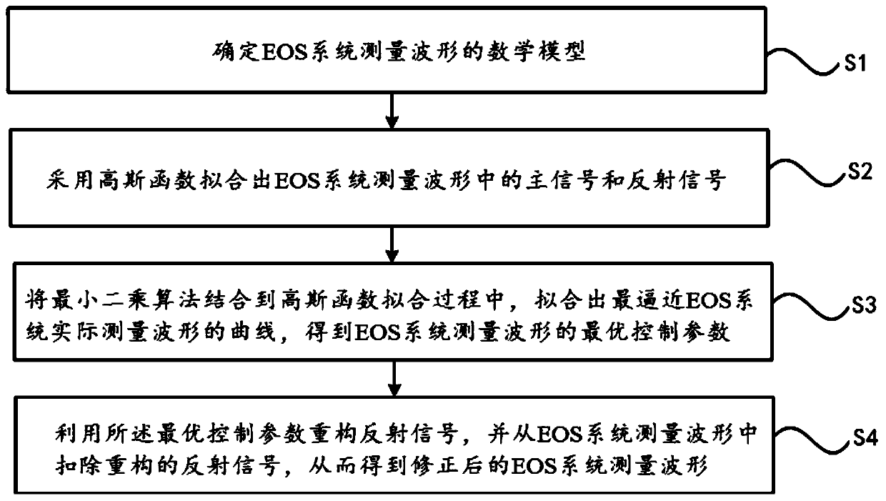
[0056] figure 2 is a flow chart of a method for correcting electro-optical sampling measurement waveforms according to an exemplary embodiment, as shown in figure 2 As shown, the method includes:

[0057] Step S1, determining the mathematical model of the waveform measured by the EOS system;

[0058] Step S2, using a Gaussian function to fit the main signal and reflected signal in the wavef...


PUM


Abstract

The invention relates to an electro-optical sampling measurement waveform correction method and system. The method comprises the following steps of determining a mathematical model of an EOS system measurement waveform, fitting a main signal and a reflection signal in the measurement waveform of the EOS system by adopting a Gaussian function, combining a least square algorithm into a Gaussian function fitting process, fitting a curve closest to the actual measurement waveform of the EOS system, and obtaining an optimal control parameter of the measurement waveform of the EOS system, and reconstructing a reflection signal by using the optimal control parameter, and deducting the reconstructed reflection signal from the EOS system measurement waveform so as to obtain a corrected EOS system measurement waveform. According to the technical scheme provided by the invention, through constructing a reflection signal waveform, the superposition problem of the main signal waveform and the reflection signal waveform in the measurement waveform is scientifically and reasonably corrected, the measured main signal waveform is effectively recovered from the actual measurement waveform of the EOSsystem, the measurement waveform distortion problem is effectively solved, and the measurement traceability of the high-speed pulse waveform parameter generated by the PD is further realized.

Description

technical field [0001] The invention relates to the technical field of electro-optic sampling, in particular to an electro-optical sampling measurement waveform correction method and system. Background technique [0002] With the development of high-speed computing and wireless broadband communication, time-domain broadband measurement technology has been widely used in baseband and RF field signal testing and product development, and the bandwidth of broadband sampling oscilloscopes has gradually increased from 50GHz to 100GHz. Due to the limitations of the measurement principle of the "Nose-to-nose" (NTN) calibration technology, it can no longer meet the demand for traceability of the broadband sampling oscilloscope. With the advancement of high-speed pulse generation technology using photoelectric means, international advanced metrology laboratories (NIST in the United States, PTB in Germany, NPL in the United Kingdom, etc.) have gradually returned to the technical route ...

Claims


Application Information

Patent Timeline
Patent Type & Authority Applications(China)
IPC IPC(8): G01R13/02
CPCG01R13/0209
Inventor 赵科佳杨智君冯志刚吴昭春陈赫
Owner NAT INST OF METROLOGY CHINA
Why Eureka
Try Eureka