Method for improving coercive force of sintered neodymium-iron-boron magnet

A technology of NdFeB and coercive force, which is applied in the field of improving the coercive force of sintered NdFeB magnets, can solve the problems of restricting the production efficiency of continuous coating equipment, affecting production efficiency, affecting the diffusion effect, etc., and shorten the pre-vacuumization Time, improve production efficiency, simplify the effect of furnace operation

Active Publication Date: 2020-06-16
EARTH PANDA ADVANCE MAGNETIC MATERIAL
View PDF5 Cites 10 Cited by
  • Summary
  • Abstract
  • Description
  • Claims
  • Application Information

AI Technical Summary

Problems solved by technology

[0004] However, the current method of direct magnetron sputtering to deposit heavy rare earth metal film layer for grain boundary diffusion also has certain deficiencies, which are mainly manifested in: (1) During the magnetron sputtering process, the magnet will have a certain degree of temperature rise, In order to prevent the heavy rare earth metal coating on the surface of the magnet from being oxidized, the magnet must be cooled to below 80°C after magnetron sputtering before discharging. In order to cool the coated magnet to below 80°C, it usually takes more than 20 minutes time, which to a large extent restricts the further improvement of the production efficiency of continuous coating equipment; (2) The magnets covered with heavy rare earth film layers must be separated from each other when they are placed in a heat treatment furnace for subsequent heat treatment. Otherwise, the two magnets that are in contact with each other will be stuck, which brings great trouble to the placement of the magnet after coating; (3) the vacuum in the furnace must be sufficiently high (usually better than 1× 10 -2 Pa), otherwise the residual air in the furnace will oxidize the heavy rare earth metal layer covered on the surface of the magnet during the heating process, affecting the diffusion effect
These deficiencies directly affect the further improvement of the production efficiency of continuous magnetron sputtering for grain boundary diffusion of sintered NdFeB magnets

Method used


Image

  • Method for improving coercive force of sintered neodymium-iron-boron magnet
  • Method for improving coercive force of sintered neodymium-iron-boron magnet
  • Method for improving coercive force of sintered neodymium-iron-boron magnet

Examples


Embodiment 1

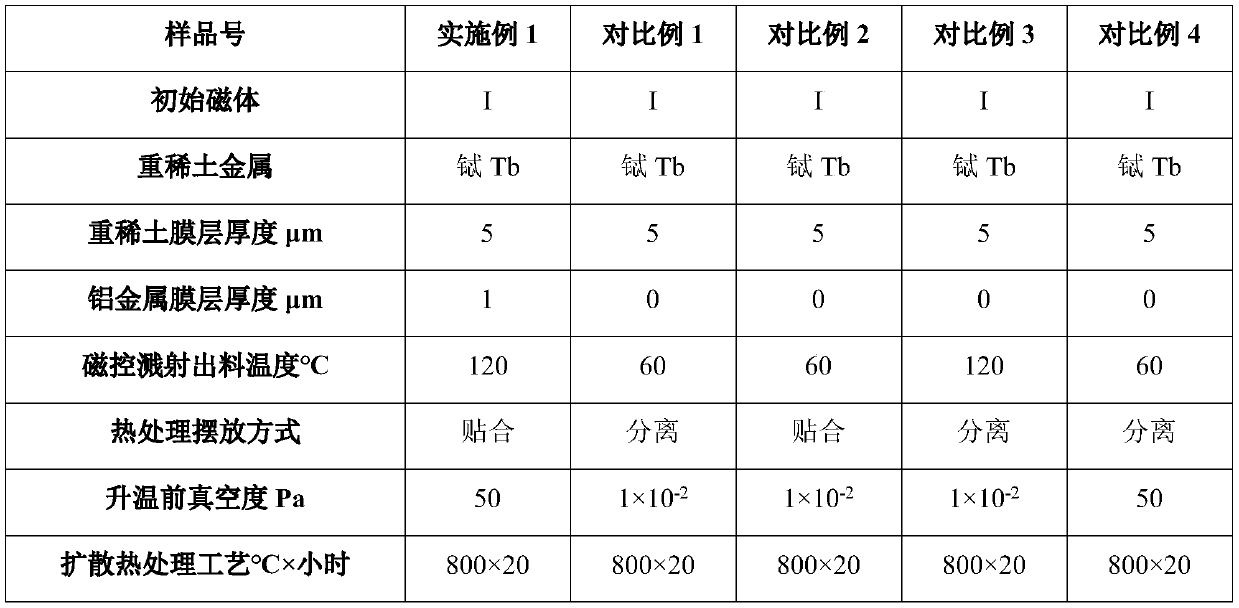
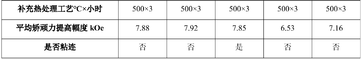
[0040] Using the 3-target continuous magnetron sputtering equipment, the magnet I with the specification of 40mm×30mm×3mm (the brand is N52, the main component is Nd 30 Fe 69 B 1 , wt.%) on two 40mm×30mm surfaces from the inside to the outside were deposited 5μm terbium metal film layer and 1μm aluminum metal film layer, when the magnet temperature was 120 ℃, it was taken out of the magnetron sputtering equipment, and the two magnets The surface coated with the film layer is put into a high-vacuum sintering furnace for high-temperature heat treatment after bonding. Before the heat treatment, the temperature in the furnace is 35°C, the vacuum degree is 50Pa, the heating rate is 10°C / min, and the temperature is kept at 800°C for 20 hours. Afterwards, high-purity argon gas was introduced to start cooling, and the magnet was taken out when cooled to 75°C, and the magnet was heat-treated at 500°C for 3 hours to obtain the magnet of Example 1.

Embodiment 2

[0055] Using 4-target continuous magnetron sputtering equipment, in the magnet II with a specification of 35mm×30mm×4mm (the grade is 50M, the main component is Nd 30 Dy 1 Fe 68 B 1 , wt.%) on two 35mm×30mm surfaces, deposit 10μm dysprosium metal film layer and 1.5μm aluminum metal film layer respectively from the inside to the outside, and take it out of the magnetron sputtering equipment when the magnet temperature is 160°C, two magnets The film layer on the surface is directly bonded and placed in a high-vacuum sintering furnace for high-temperature heat treatment. Before heat treatment, the temperature in the furnace is 35°C, the vacuum degree is 80Pa, and the heating rate is 10°C / min. After holding at 850°C for 30 hours, Introduce high-purity argon gas to start cooling. When the magnet is cooled to 75° C., the magnet is taken out, and the magnet is heat-treated at 460° C. for 5 hours to obtain the magnet of Example 2.

Embodiment 3

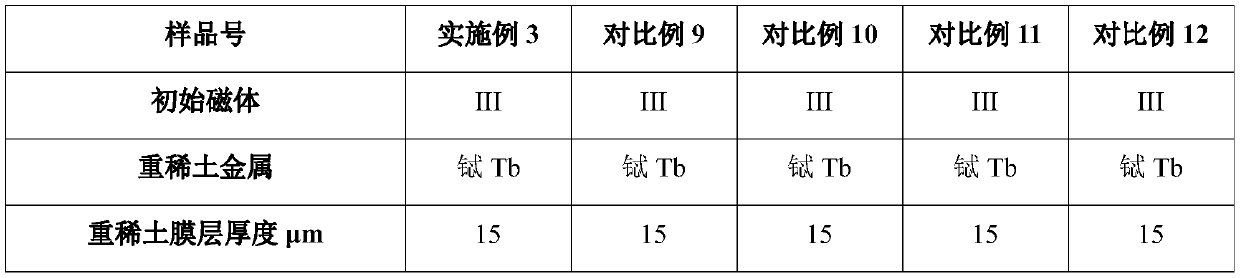
[0069] Using 5-target continuous magnetron sputtering equipment, in the magnet III with a specification of 30mm×25mm×6mm (the grade is 50H, the main component is Nd 30 Tb 1 Fe 68 B 1 , wt.%) two 30mm×25mm surfaces were deposited from the inside to the outside 15μm terbium metal film layer and 2μm aluminum metal film layer, when the magnet temperature was 200 ℃, it was taken out of the magnetron sputtering equipment, the two magnet surfaces After the film layer is directly bonded, it is placed in a high-vacuum sintering furnace for high-temperature heat treatment. Before the heat treatment, the temperature in the furnace is 35°C, the vacuum degree is 100Pa, and the heating rate is 10°C / min. After holding at 880°C for 40 hours, pass Enter high-purity argon gas to start cooling, take out the magnet when cooling to 75°C, and obtain the magnet of Example 3 after the magnet is heat-treated at 550°C for 6 hours.


PUM

PropertyMeasurementUnit
thicknessaaaaaaaaaa
thicknessaaaaaaaaaa

Abstract

The invention discloses a method for improving the coercive force of a sintered neodymium-iron-boron magnet. The method comprises the steps of sequentially plating the surface of the sintered neodymium-iron-boron magnet from inside to outside by adopting multi-target continuous magnetron sputtering to form a heavy rare earth metal film layer and a metal aluminum film layer, and discharging to obtain a semi-finished product; and placing the semi-finished product in a pre-vacuumizing environment to be subjected to heat treatment and then cooling to prepare the high-coercivity sintered neodymium-iron-boron magnet , wherein vacuumizing is continuously conducted in the heat treatment process. According to the method, the dischargeable temperature after magnetron sputtering coating is increased, so that the cooling time is shortened; the subsequent charging operation is simplified; and the method has the advantages of saving energy and improving the production efficiency.

Description

technical field [0001] The invention belongs to the field of rare earth permanent magnet materials, and in particular relates to a method for increasing the coercive force of a sintered NdFeB magnet. Background technique [0002] Sintered NdFeB magnets are the most magnetic materials so far. They are widely used in aerospace, automobile industry, electronic appliances, medical equipment, energy-saving motors, new energy, wind power and other fields. The most promising permanent magnet material. Sintered NdFeB magnets have outstanding advantages such as high magnetic energy product, high coercive force, high energy density, high cost performance and good mechanical properties, and have played an important role in the high-tech field. After more than 30 years of research and development, a reasonable alloy composition and a mature preparation process have been designed, so that the remanence and maximum energy product of the sintered NdFeB magnet reach more than 90% of the th...

Claims


Application Information

Patent Timeline
Patent Type & Authority Applications(China)
IPC IPC(8): H01F41/02H01F1/057
CPCH01F41/0253H01F41/0293H01F1/057H01F1/0577
Inventor 刘友好查善顺冯泉妤陈静武衣晓飞
Owner EARTH PANDA ADVANCE MAGNETIC MATERIAL
Why Eureka
Try Eureka