Free sub-sampling type row logic circuit for image sensor and working method thereof

An image sensor and logic circuit technology, applied in image communication, television, electrical components, etc., can solve the problems of decoding circuit irregularity, incompetent line decoding circuit, low frame rate, etc., to reduce the loss of dynamic power consumption , to achieve the effect of fast startup and reducing dynamic power consumption

Active Publication Date: 2020-06-16
XIAN MICROELECTRONICS TECH INST
View PDF4 Cites 2 Cited by
  • Summary
  • Abstract
  • Description
  • Claims
  • Application Information

AI Technical Summary

Problems solved by technology

[0003] Most traditional image sensors directly use line decoding to complete the control of the pixel area array. Although the design structure is simple, the function is single, and the freedom of area array configuration is not high.
Due to the influence of the size of the area array image sensor, the frame rate is often low, and the traditional line decoding circuit does not have the sub-sampling function, so the frame rate can be quickly increased under the premise of low resolution requirements and the need to keep the window size unchanged. When the traditional row decoding circuit is often not competent, the application range of this type of image sensor is limited.
[0004] With the development of technology, some image sensor products have begun to introduce sub-sampling function, but it is still implemented by decoding logic. Therefore, the sub-sampling configuration is limited to specific types, and the degree of configuration freedom is not enough. It is impossible to realize the arbitrary number of interval lines and the window opening position. Flexible free subsampling
When the size of the pixel array is large, it is easy to have defective pixels. Since it is impossible to debug a single row of pixels, it is also difficult to quickly locate the pixel defect position of the finished circuit.
In particular, for ultra-large array image sensors, since chip implementation often needs to be completed through multiplexing and splicing, it is difficult for this type of sensor chip to support layout multiplexing due to the irregularity of the decoding circuit.

Method used


Image

  • Free sub-sampling type row logic circuit for image sensor and working method thereof
  • Free sub-sampling type row logic circuit for image sensor and working method thereof
  • Free sub-sampling type row logic circuit for image sensor and working method thereof

Examples


Embodiment Construction

[0039]The present invention will be further described in detail below in conjunction with specific embodiments, which are explanations of the present invention rather than limitations.

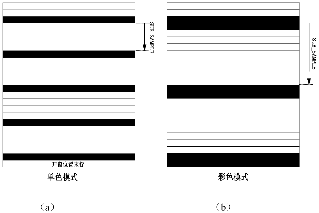
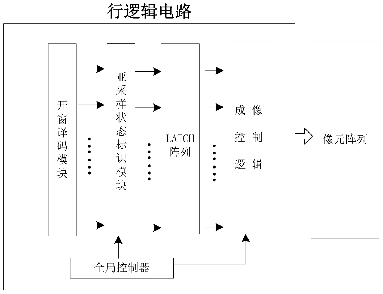
[0040] The row logic circuit is the controller used to generate the switch signal of the pixel array MOS tube in the image sensor, which solves the timing problem when the pixel array performs reset, exposure and readout activities in different exposure modes, and at the same time completes the image sensor in the pixel array. Functions such as windowing, merging, and subsampling in the array row direction. Image subsampling can quickly increase the system frame rate by reducing a certain number of pixels while maintaining the same window size.

[0041] The subsampling diagram is as follows figure 1 As shown, for monochrome image sensor applications, the default active line is one line, and for color image sensor applications, in order to maintain the integrity of the Bayer pattern, the subsa...


PUM


Abstract

The invention belongs to the technical field of image sensors, and discloses a free sub-sampling type row logic circuit for an image sensor and a working method thereof. According to the invention, through a windowing decoding module, a sub-sampling state identification module, a LATCH array, a global controller and an imaging control logic module, control of pixel rows of the image sensor is completed; a plurality of exposure modes are supported; full-array free sub-sampling of the super-large-scale pixel array is realized through sub-sampling identification of the pixel array; through the design of an address identifier and a sub-sampling pointer chain, a small-area sub-sampling mark in a windowing range is supported; subsampling one-key turn-off is supported; through clock gating design, the sub-sampling identification and the pixel imaging work frequency are different, and sub-sampling rapid calibration is realized. The free sub-sampling type row logic circuit is simple in design structure, flexible in configuration, wide in application range and capable of supporting multiplexing and splicing and can be applied to different types of image sensor chip circuits.

Description

technical field [0001] The invention belongs to the technical field of CMOS image sensors, and in particular relates to a free subsampling type row logic circuit for an image sensor and a working method thereof. Background technique [0002] The image sensor is one of the core components in the image acquisition equipment. It can convert the charge generated by the photosensitive element in the pixel structure into a voltage signal output at a very fast speed. It is widely used in aerospace, astronomical observation, biotechnology and consumer electronics, etc. in the field. Generally speaking, when the number of pixels in an image sensor is large and the size of a single pixel is large, better image quality, observation range and color expression can be obtained, so large area array image sensors have gained widespread attention as high-end imaging components , the market demand is also increasing. [0003] Most traditional image sensors directly use line decoding to comp...

Claims


Application Information

Patent Timeline
Patent Type & Authority Applications(China)
IPC IPC(8): H04N5/374H04N5/378H04N5/353
CPCH04N25/53H04N25/768H04N25/76H04N25/75
Inventor 张先娆李婷吴龙胜王雯徐晚成张曼
Owner XIAN MICROELECTRONICS TECH INST
Why Eureka
Try Eureka