Micro-clamping robot

A robot and micro-clamping technology, applied in the direction of micro-manipulators, chucks, manipulators, etc., can solve the problem that the jaws no longer move in parallel

Active Publication Date: 2020-06-19
CHONGQING UNIV
View PDF12 Cites 8 Cited by
  • Summary
  • Abstract
  • Description
  • Claims
  • Application Information

AI Technical Summary

Problems solved by technology

The currently developed micro-clamping robot can move the jaws in parallel when it is unloaded, but in order to realize the clamping force se

Method used


Image

  • Micro-clamping robot
  • Micro-clamping robot
  • Micro-clamping robot

Examples


Embodiment 1

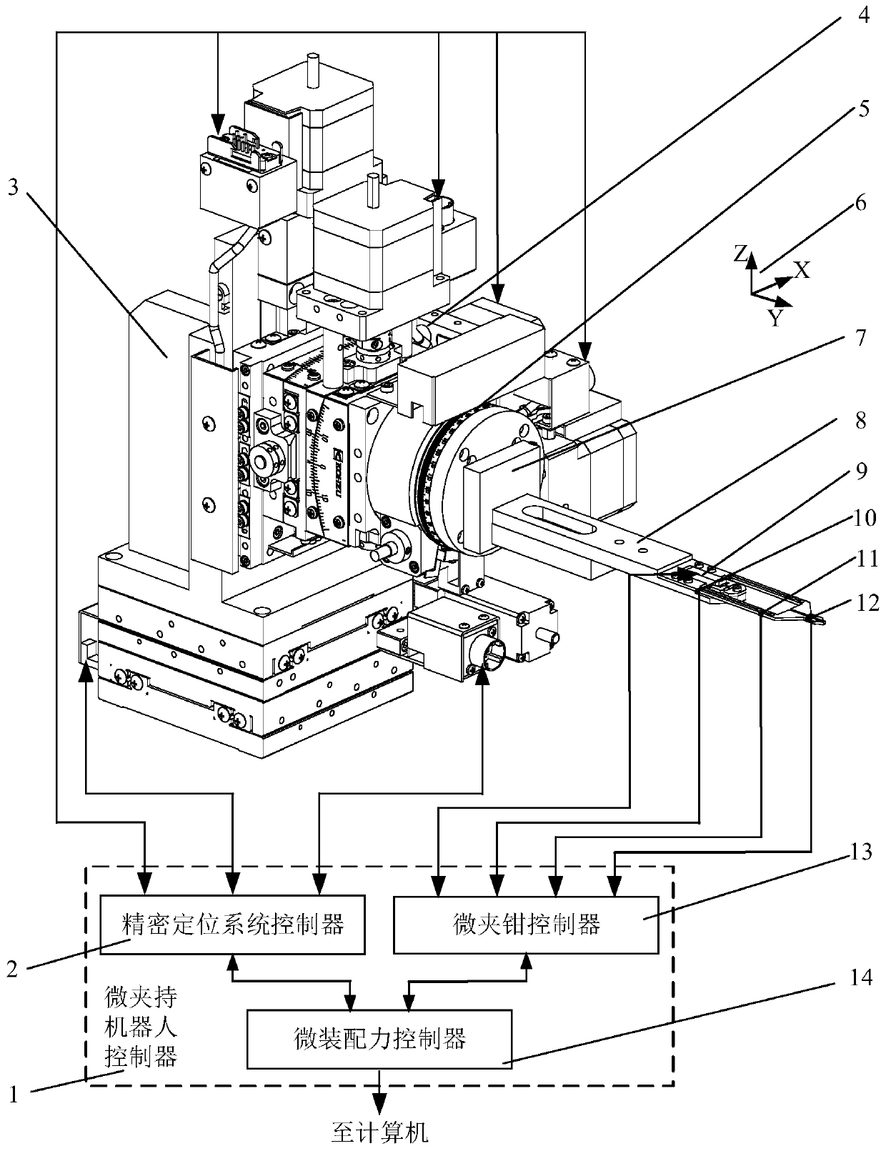
[0076] Such as figure 1 The shown micro clamping robot that can realize six-degree-of-freedom space movement, the robot is realized by a precision electric table 3 that can move linearly along the X-axis, Y-axis and Z-axis to achieve three freedoms along the X-axis, Y-axis and Z-axis respectively. The two-axis precision electric rotary table 4 that can rotate along the X axis and the Z axis realizes the rotary motion along the X axis and the Z axis respectively, and the precision electric rotary table 5 that can rotate along the Y axis realizes the rotary motion along the Y axis. The rotational movement of the shaft; the clamping and releasing of tiny devices is realized by using the micro-clamp that integrates the jaw displacement sensing unit, the clamping force sensing unit and the micro-assembly force sensing unit at the same time. The micro gripper is installed on the micro gripper and precision positioning system adapter 7 through the base 8 . And the precision electric...

Embodiment 2

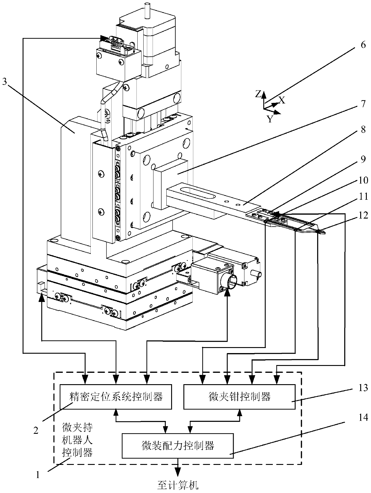
[0083] Such as figure 2 Shown is a three-degree-of-freedom micro-clamping robot consisting of a precision electric platform 3 that can move linearly along the X-axis, Y-axis, and Z-axis. The robot can move linearly along the X-axis, Y-axis, and Z-axis The precision electric platform 3 realizes the linear motion along the X-axis, Y-axis and Z-axis, and realizes the micro-gripper which integrates the jaw displacement sensing unit, the clamping force sensing unit and the micro-assembly force sensing unit at the same time. clamping and releasing. The clamping process of the tiny parts performed by the micro grippers is consistent with the process of Example 1.

[0084] It is also possible to change the structure of the micro-clamping robot by processing different structures of the jaw displacement, clamping force and micro-assembly force sensing mechanism on the micro-clamp single-piece compliant mechanism, and the specific implementation process is consistent with Example 1 . ...

Embodiment 3

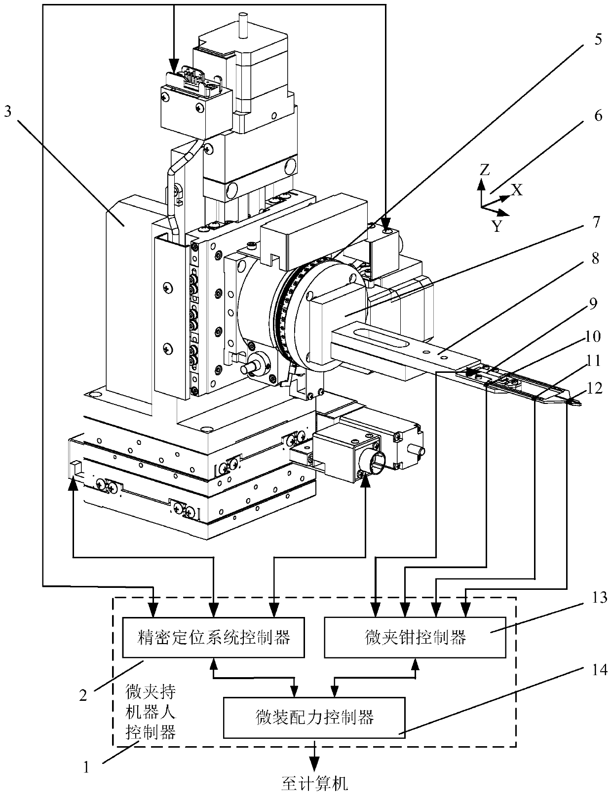
[0086] Such as image 3Shown is a four-degree-of-freedom micro-clamping robot consisting of a precision electric platform 3 that can move linearly along the X-axis, Y-axis, and Z-axis, and a precision electric rotary table that can rotate along the Y-axis. The precision electric platform 3 that moves linearly along the X-axis, Y-axis and Z-axis realizes the linear movement along the X-axis, Y-axis and Z-axis, and the precision electric rotary table that can rotate along the Y-axis realizes the rotational movement along the Y-axis. The micro gripper integrating jaw displacement sensing unit, clamping force sensing unit and micro-assembly force sensing unit realizes the clamping and releasing of tiny parts. The clamping process of the tiny parts performed by the micro gripper is consistent with the clamping process in Example 1.

[0087] It is also possible to change the structure of the micro-clamping robot by processing different structures of jaw displacement, clamping force...


PUM


Abstract

The invention relates to a micro-clamping robot. According to the robot, micro parts can be clamped, high-precision motion positioning can be achieved, and meanwhile, the detection and feedback control over clamping jaw displacement, clamping force and micro-assembly force can be achieved. The micro-clamping robot is composed of a micro-clamp which can achieve clamping jaw displacement detection,clamping force detection and micro-assembly force detection at the same time, a precision positioning system and a micro-clamping robot controller, linear motion and rotary motion along X axis, Y axisand Z axis are achieved, and meanwhile, detection, sense and feedback of clamping jaw displacement, clamping force and micro-assembly force can be achieved at the same time; the micro-clamp is composed of a base, a single-piece compliant mechanism fixed on the base, an actuator and a micro-clamp controller; and first-stage lever mechanisms which are symmetrically arranged, third-stage series parallelogram mechanisms which are symmetrically arranged and clamping jaws which are symmetrically arranged are arranged on the single-piece compliant mechanism.

Description

technical field [0001] The invention relates to the field of micro-assembly, in particular to a micro-clamping robot. Background technique [0002] With the rapid development of micro-nano device manufacturing technology, the demand for heterogeneous heterogeneous non-silicon micro-nano devices and systems has gradually emerged and increased. Most of the parts required by these technologies have complex three-dimensional geometric structures and are made of different materials, and microassembly technology is an important way to realize the integration of heterogeneous and heterogeneous non-silicon microsystems. The micro-gripper robot is the end effector system of the micro-assembly system, and its grippers are in direct contact with the object to be clamped. Therefore, the research on the micro-gripper robot is very important for the micro-assembly technology. As a typical micro-actuator, the micro-clamping robot has a good application prospect in the processing of micro-...

Claims


Application Information

Patent Timeline
IPC IPC(8): B23P19/00B25J7/00B25J9/12B25J9/16B25J15/02
CPCB23P19/00B23P19/007B25J7/00B25J9/12B25J9/1602B25J9/1694B25J9/1633B25J15/0206
Inventor 王代华包丽萍王坎赵建宇
Owner CHONGQING UNIV
Why Eureka
Try Eureka