Robot joint torque control system and load compensation method thereof

A technology of robot joints and control systems, applied in the direction of program-controlled manipulators, manipulators, manufacturing tools, etc., can solve problems such as complex control method models, achieve the effects of increasing open-loop gain, simple application, and improving system performance

Active Publication Date: 2020-06-19
BEIJING INSTITUTE OF TECHNOLOGYGY
View PDF4 Cites 2 Cited by
  • Summary
  • Abstract
  • Description
  • Claims
  • Application Information

AI Technical Summary

Problems solved by technology

However, many advanced control methods such as quantitative feedback control and robust control can achieve good control effects, but t

Method used


Image

  • Robot joint torque control system and load compensation method thereof
  • Robot joint torque control system and load compensation method thereof
  • Robot joint torque control system and load compensation method thereof

Examples


Embodiment Construction

[0024] The present invention will be further described below in conjunction with the accompanying drawings and specific embodiments, but the protection scope of the present invention is not limited thereto.

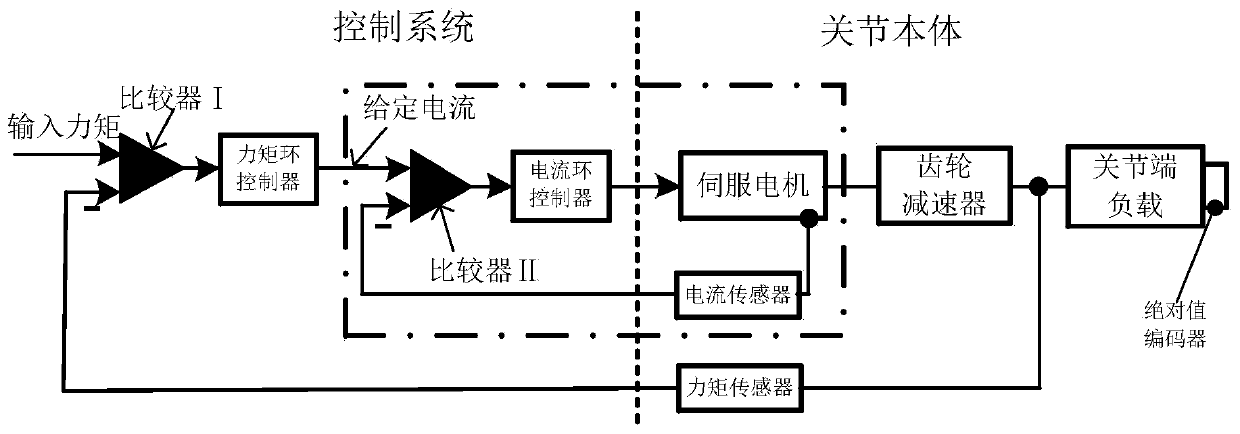
[0025] like figure 1 As shown, the robot joint torque control system is composed of the joint body and the control system. The joint body is composed of a servo motor, a gear reducer, a torque sensor, and an absolute encoder. The output shaft of the servo motor is rigidly connected to the gear reducer, and the gear reducer is rigidly connected to the load at the joint end through a torque sensor. The torque sensor is used to detect joints. The actual torque at the end; the current sensor is installed inside the servo motor to detect the actual output current of the servo motor, and the absolute encoder is installed at the joint end load to detect the actual position of the joint end load. The control system is composed of comparator I, torque loop controller, comparator ...


PUM


Abstract

The invention provides a robot joint torque control system and a load compensation method thereof, and belongs to the technical field of robot joint motion control. Firstly a mathematical model of therobot joint torque control system is built, equivalent deformation is carried out on a system functional block diagram, it can be seen that load parameters have great influence on joint torque output, and by designing a load compensation controller, the influence of the load parameters on the joint torque output is effectively eliminated. On the basis of compensation, the system is equivalent toan inertial element, then by adjusting PD controller parameters to increase system open-loop gains, the system bandwidth is improved, the response speed of the robot joint torque control system is improved, and thus the robot joint torque control system performance is improved.

Description

technical field [0001] The invention belongs to the technical field of robot joint motion control, and in particular relates to a robot joint torque control system and a load compensation method thereof. Background technique [0002] In recent years, robots have been used more and more widely in all walks of life in society, making the research of robots a hot spot. Commonly used driving methods for robots include motor drive, hydraulic drive and pneumatic drive. Motor drive has the advantages of compact structure, simple control, high transmission efficiency, and high control precision. It is currently the most commonly used drive method in the field of robotics. Robotic joints are usually composed of servo motors, gear reducers, and encoders, and use a typical position control system. However, when the foot touches the bottom or touches an obstacle, if the position control system continues to be used, it will cause a large rigid impact, resulting in Operations such as wa...

Claims


Application Information

Patent Timeline
IPC IPC(8): B25J9/16
CPCB25J9/1633B25J9/1628B25J9/1638G05B2219/39188B25J13/085G05B19/4155
Inventor 余张国刘雅梁黄强左昱昱陈学超于晗黄高
Owner BEIJING INSTITUTE OF TECHNOLOGYGY
Why Eureka
Try Eureka