Laser confocal/differential confocal Raman spectrum vibration parameter measurement method

A vibration parameter and vibration measurement technology, applied in the direction of measuring devices, measuring ultrasonic/sonic/infrasonic waves, using wave/particle radiation, etc.

Active Publication Date: 2020-06-19
BEIJING INSTITUTE OF TECHNOLOGYGY
View PDF16 Cites 5 Cited by
  • Summary
  • Abstract
  • Description
  • Claims
  • Application Information

AI Technical Summary

Problems solved by technology

A method for measuring vibrational parameters of laser confocal / differential confocal Raman spectroscopy is proposed

Method used


Image

  • Laser confocal/differential confocal Raman spectrum vibration parameter measurement method
  • Laser confocal/differential confocal Raman spectrum vibration parameter measurement method
  • Laser confocal/differential confocal Raman spectrum vibration parameter measurement method

Examples


Embodiment 1

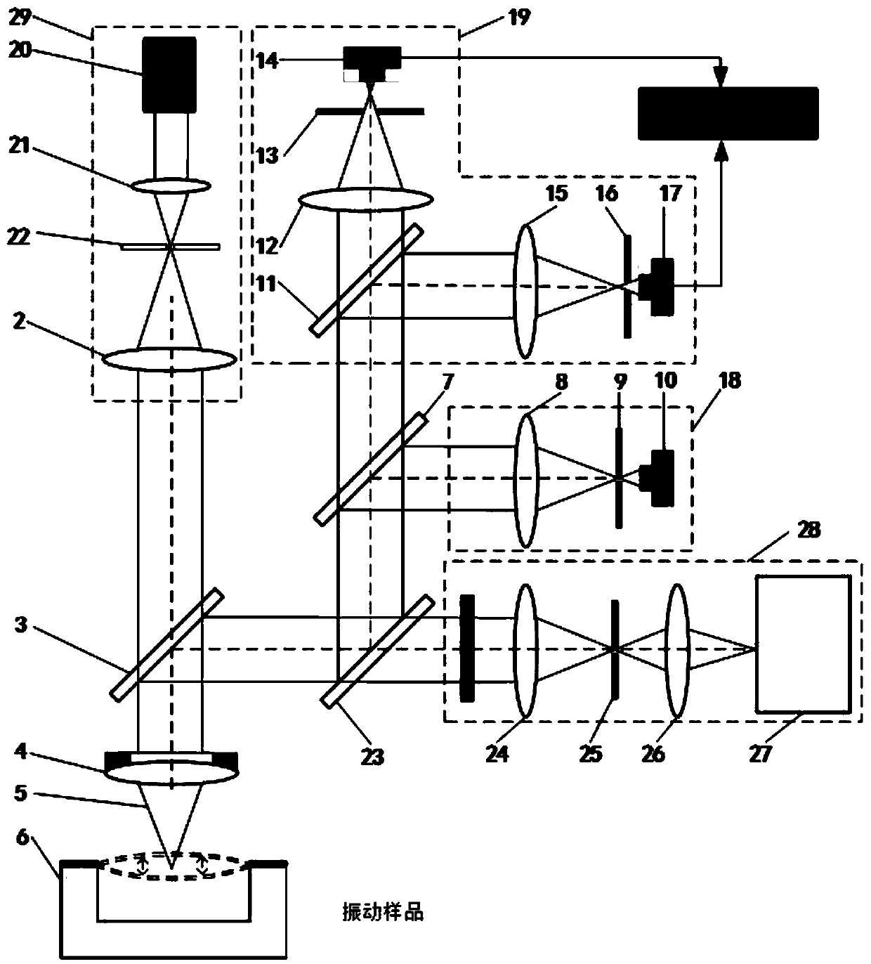
[0068] When only the confocal vibration parameter measurement system is used to measure the vibration parameters, and the spectrum detection system is used to process the received Raman scattered light, a laser confocal / differential confocal Raman spectrum vibration parameter measurement method is shown in the attached image 3 As shown, the specific steps are as follows:

[0069] a) According to the characteristics of the confocal axial response curve, the optimal test interval is defined on the normalized axial response curve I(u) [-3u 0 ,-u 0 ] and [u 0 ,3u 0 ], where u 0 is a point on the main lobe of the confocal axial response curve. On the optimal test interval, the confocal axial response curve has the highest sensitivity to axial displacement. For the difference in amplitude, the amplitude A 0 Divided into three ranges, large, medium and small, respectively A 0 ≤ u 0 , u 0 0 ≤3u 0 and 3u 0 0 ≤W.D, use measurement mode 1 to measure amplitude A 0 ≤u 0 Vibra...

Embodiment 2

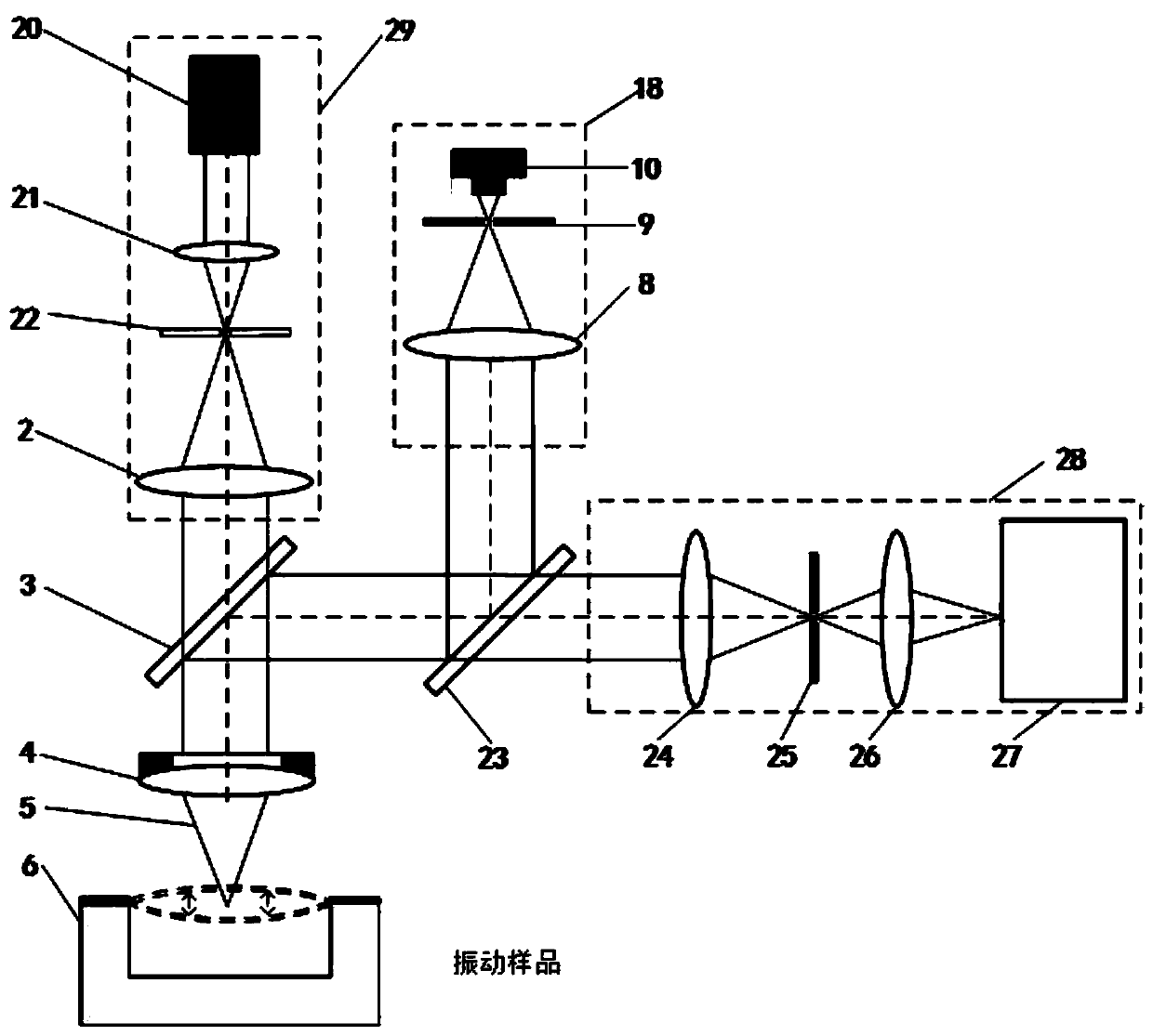
[0086] When only the differential confocal vibration parameter measurement system is used to measure the vibration parameters, and the received Raman scattered light is processed by the spectral detection system, a laser confocal / differential confocal Raman spectrum vibration parameter measurement method is as follows: attached Figure 7 As shown, the specific steps are as follows:

[0087] a) According to the characteristics of the differential confocal axial response curve, the optimal test interval is defined on the normalized axial response curve [-u 1 ,u 1 ], where u 1 is a point on the differential confocal axial response curve, in the optimal test interval [-u 1 ,u 1 ], the differential confocal axial response curve has high sensitivity to axial displacement.

[0088] Place the sample to be measured behind the measurement objective lens, adjust the sample to be measured so that it is on the same optical axis as the measurement beam, and at the same time make the st...


PUM


Abstract

The invention discloses a laser confocal/differential confocal Raman spectrum vibration parameter measurement method, and belongs to the technical field of optical precision measurement. Confocal vibration detection, differential confocal vibration detection and Raman spectrum detection technologies are fused, nondestructive separation is carried out on Rayleigh light and Raman scattered light byutilizing a dichroic light splitting system, spectrum detection is carried out on the Raman scattered light, and vibration parameter detection such as amplitude and frequency is carried out on the Rayleigh light. Therefore, the vibration information testing method capable of simultaneously detecting the vibration parameters of the sample micro-area and the Raman spectrum of the vibration of the sample micro-area is formed. According to the invention, the confocal Raman microscope and the differential confocal Raman microscope have the capability of simultaneously detecting micro-area vibrationparameter information and the Raman spectrum of micro-area vibration. The method has the advantages of high vibration measurement precision, wide amplitude measurement range, high frequency measurement bandwidth, high spectrum detection sensitivity, capability of measuring periodic motion and aperiodic motion, high environmental interference resistance and the like. Meanwhile, high-precision detection of micro-area vibration parameters and vibration spectral characteristics is carried out, and the method has a wide application prospect in the technical field of optical precision measurement.

Description

technical field [0001] The invention relates to a laser confocal / differential confocal Raman spectrum vibration parameter measurement method, which belongs to the technical field of optical precision measurement. [0002] technical background [0003] At present, various sensors based on MEMS have been widely used in various fields such as biology, medicine, industry, aviation, military, communication, etc. MEMS devices have gradually become a research hotspot in the field of micro / nano engineering. Micromechanical structures (MEMS) with out-of-plane vibration implement system functions based on mechanical motion or deformation, and their performance is determined by the dynamic characteristics of the resonant element. Nanoelectromechanical systems can be used as ultrasensitive mass sensors and ultrahigh frequency resonators, and can also be used to explore fundamental physical phenomena such as nonlinear damping and quantum effects in macroscopic objects. Various dissipatio...

Claims


Application Information

Patent Timeline
Patent Type & Authority Applications(China)
IPC IPC(8): G01H9/00
CPCG01H9/00
Inventor 赵维谦何奇邱丽荣
Owner BEIJING INSTITUTE OF TECHNOLOGYGY
Why Eureka
Try Eureka