High-efficiency continuous ammonia gas recovery system and use method thereof

A recovery system and ammonia gas technology, applied in separation methods, chemical instruments and methods, and dispersed particle separation, etc., can solve the problems of low ammonia absorption efficiency, need to wait for discharge, and low ammonia absorption efficiency, so as to improve the effect and improve High absorption effect, ammonia absorption efficiency

Inactive Publication Date: 2020-06-26
SHANOGUAN KAIHONG NANOMATERIAL
View PDF0 Cites 4 Cited by
  • Summary
  • Abstract
  • Description
  • Claims
  • Application Information

AI Technical Summary

Problems solved by technology

[0003] The recovery of ammonia usually requires the use of the principle that ammonia is easily soluble in water to recover ammonia. In the existing ammonia absorption device, there is a process of using spraying to absorb ammonia, but only the process of ammonia absorption by spraying is used. The absorption efficiency of ammonia is low, and the process of spraying and absorbing ammonia takes a long time
In addition, the spray absorbing device for spraying ammonia cannot continuously absorb ammonia when the ammonia water pool is discharged, resulting in the need to wait for the discharge of ammonia during the ammonia absorption process, and the efficiency of ammonia absorption is low

Method used


Image

  • High-efficiency continuous ammonia gas recovery system and use method thereof
  • High-efficiency continuous ammonia gas recovery system and use method thereof
  • High-efficiency continuous ammonia gas recovery system and use method thereof

Examples


Embodiment Construction

[0036] The specific implementation manners of the present invention will be further described in detail below in conjunction with the accompanying drawings and embodiments. The following examples are used to illustrate the present invention, but are not intended to limit the scope of the present invention.

[0037] like Figure 1 to Figure 6 As shown, a high-efficiency continuous recovery system for ammonia in a preferred embodiment of the present invention can improve the absorption efficiency of ammonia.

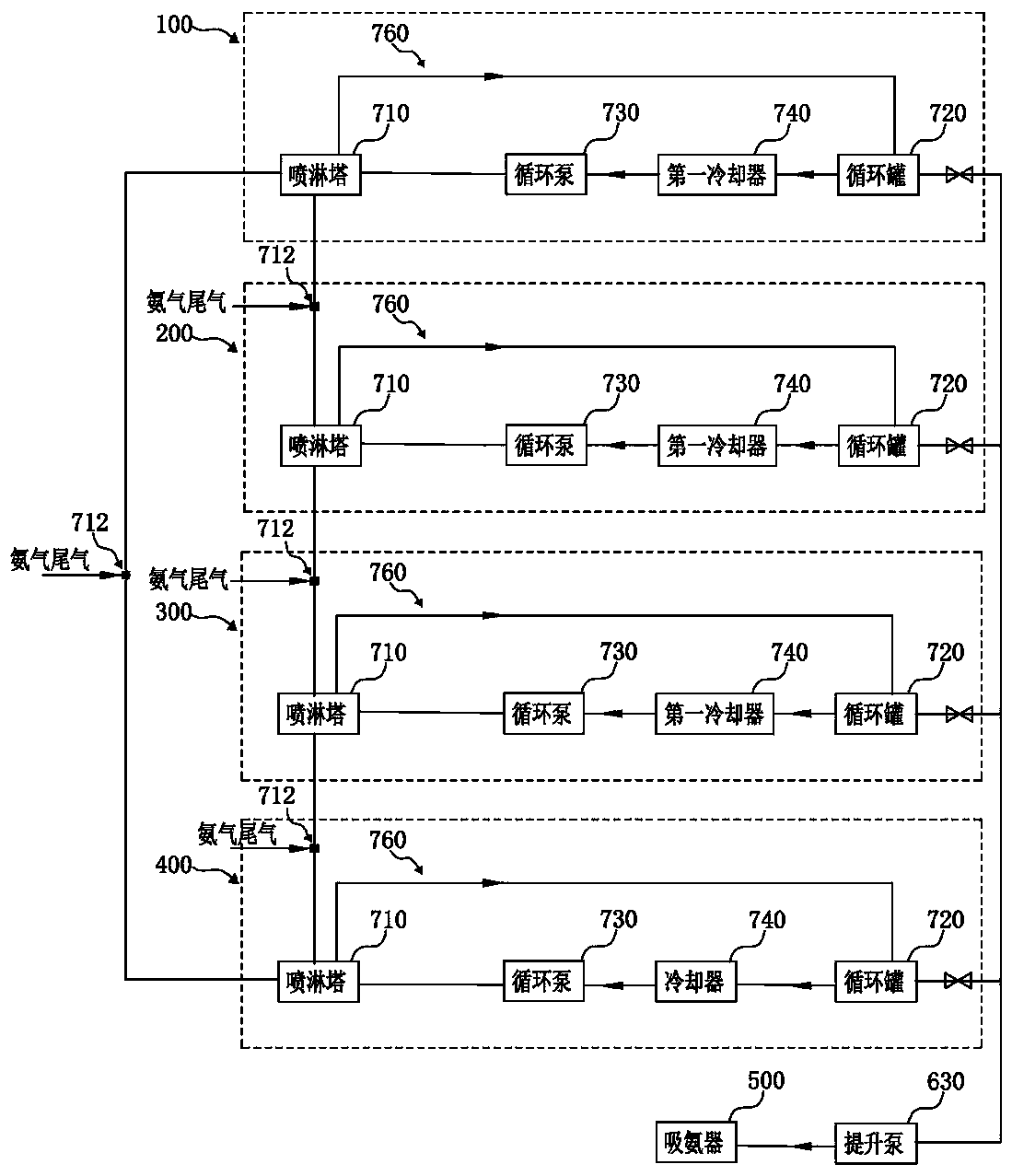
[0038] Based on the above technical solution, this embodiment provides an efficient and continuous ammonia recovery system, including a first ammonia absorption unit 100, a second ammonia absorption unit 200, a third ammonia absorption unit 300 and a fourth ammonia absorption unit 400, the first The ammonia absorption unit 100 , the second ammonia absorption unit 200 , the third ammonia absorption unit 300 and the fourth ammonia absorption unit 400 are used for spraying a...


PUM


Abstract

The invention relates to the technical field of ammonia gas recovery equipment, and discloses a high-efficiency continuous ammonia gas recovery system. Each of a first ammonia absorption unit, a second ammonia absorption unit, a third ammonia absorption unit and a fourth ammonia absorption unit comprises a spray tower and a circulating tank, spray towers of the first ammonia absorption unit, the second ammonia absorption unit, the third ammonia absorption unit and the fourth ammonia absorption unit are connected in sequence, the spray tower of the fourth ammonia absorption unit is connected tothe spray tower of the first ammonia absorption unit, an ammonia absorption switching valve is arranged on a connecting pipeline between the spray towers, the ammonia absorption switching valve can connect or disconnect the adjacent spray towers, and ammonia tail gas can be introduced from the ammonia absorption switching valve; and the system also includes an ammonia absorber, which can be respectively connected to ammonia water outlets on the circulating tanks one by one. The invention further provides a use method of the high-efficiency continuous ammonia gas recovery system. According tothe invention, the ammonia absorption effect can be improved, and continuous ammonia absorption of the high ammonia absorber can be guaranteed through the ammonia absorption units.

Description

technical field [0001] The invention relates to the technical field of ammonia gas recovery equipment, in particular to an ammonia gas high-efficiency continuous recovery system and its use method. Background technique [0002] In the process of preparing zinc oxide by the ammonia method, ammonia water is used for zinc complexation, and ammonia distillation is used to realize the crystallization of zinc ions. The complexation of ammonia, the whole process is the recycling process of ammonia. In the ammonia-based zinc oxide process, ammonia water is an important production auxiliary material. Often, many factories do not pay attention to the recovery of ammonia gas during the production process, resulting in the discharge of ammonia water into the surrounding environment and causing ammonia pollution. Therefore, it is necessary to make ammonia gas The recovery of ammonia can not only improve the efficiency of ammonia utilization, but also protect the environment. [0003] T...

Claims


Application Information

Patent Timeline
IPC IPC(8): B01D53/18
CPCB01D53/1406B01D53/1418B01D53/18
Inventor 傅智健梁鹤贤陈升刘优强张敏平
Owner SHANOGUAN KAIHONG NANOMATERIAL
Why Eureka
Try Eureka