
Aging device for automatic radar production line

An automatic production line and aging device technology, applied to conveyor control devices, transportation and packaging, conveyor objects, etc., can solve the problems of PCBA invisible damage, high production cost, low production efficiency, etc., to save length space and high production efficiency , the effect of reducing the floor area

Pending Publication Date: 2020-06-26
长沙莫之比智能科技有限公司
View PDF0 Cites 3 Cited by
  • Summary
  • Abstract
  • Description
  • Claims
  • Application Information

AI Technical Summary

Problems solved by technology

[0003] The existing radar assembly adopts the traditional manual assembly mode. Manual assembly is easy to cause invisible damage to the PCBA, affecting the product qualification rate, and the production cost is high, the production efficiency is low, and the quality of the assembled radar products is not uniform.
The existing production line models in the market usually have discrete assembly, testing, and aging stations, and the flexibility of the production line is poor. Many product models are difficult to manufacture compatiblely. The entire production line does not have overall process continuity and low efficiency. Manual online assistance is still required.

Method used


Image

  • Aging device for automatic radar production line
  • Aging device for automatic radar production line
  • Aging device for automatic radar production line

Examples


Embodiment 1

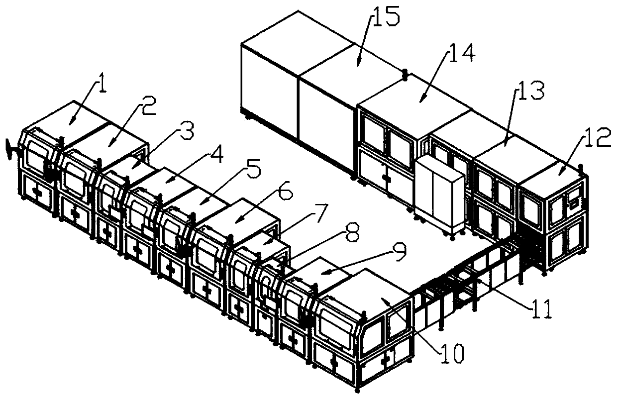
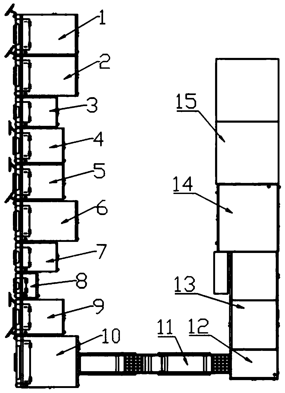
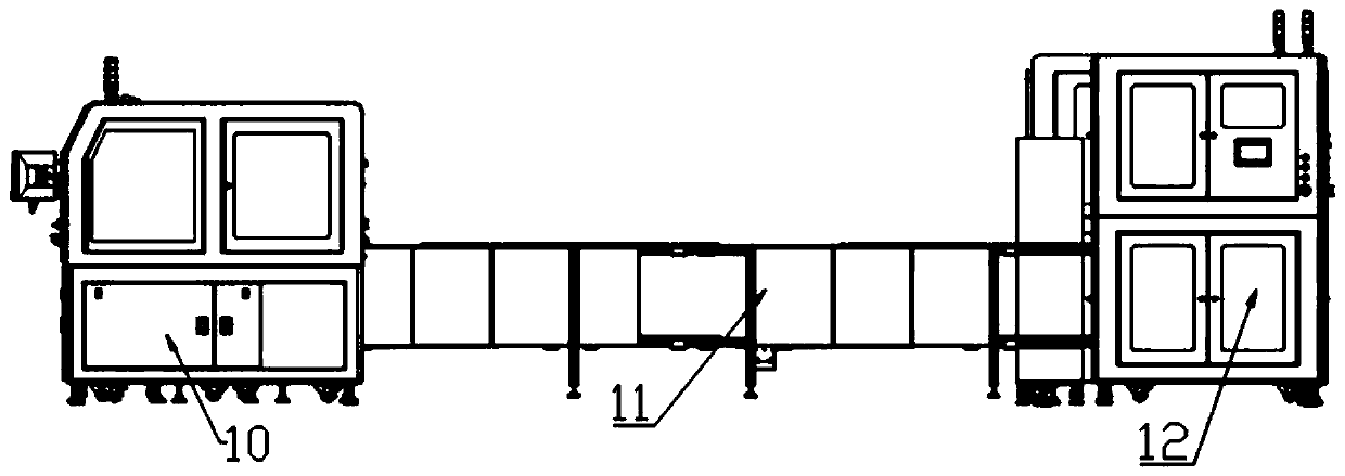
[0044] A millimeter-wave radar automated intelligent production line, as attached Figure 1~3 As shown, it includes 15 units in turn: cover plate feeding machine (1), PCBA plate feeding machine (2), PCBA board marking machine (3), PCBA board and cover plate assembly machine (4), heat conduction sheet machine (5), waterproof base feeding machine (6), waterproof base marking machine (7), pressure holding machine (8), waterproof base assembly machine (9), air tightness testing machine (10), double-layer transportation Belt conveyor (11), aging box feeder (12), aging box (13), finished product discharging machine (14), dark box test unit (15), the automatic intelligent production line of millimeter wave radar adopts U-shaped line Layout, the cover board feeder (1), PCBA board feeder (2), PCBA board marking machine (3), PCBA board and cover board assembly machine (4), heat conducting sheet paste machine (5), The waterproof base feeding machine (6), the waterproof base marking mach...

Embodiment 2

[0075] as attached Figure 22 As shown, the dark box test can also adopt the mode of off-line test to set up a dark box test room. Personnel enter and exchange radar products. The radar products are placed on the anechoic radar turntable module (16-2). The darkroom radar turntable module (16-2) is designed on the same principle as the radar turntable module (15-2). The darkroom radar turntable module (16-2) is installed on the turntable track (16-6), and the turntable track (16-6) is 0.5 to 1 meter long, and other parts of the darkroom linear slide rail (16-3), darkroom Arc-shaped slide rail (16-4), darkroom target simulator (16-5) and linear slide rail (15-3), darkroom arc-shaped slide rail (15-4), darkroom target simulator (15-5) The principle and structure are the same, and the anechoic chamber can simulate and test the performance of the radar in motion by setting the turntable track (16-6).

[0076] Other Alternative Embodiments


PUM


Abstract

The invention provides an aging device for an automatic radar production line. The aging device includes a double-layer transport belt conveyor (11), an aging oven feeder (12) and an aging oven (13),the double-layer transport belt conveyor (11) is used for storing radar products to be aged placed in aging trays, the aging oven (13) includes a plurality layers of aging conveyer belt lines (13-2),the aging oven feeder (12) includes a set of aging tray feeding lifting conveyer belt module, the aging tray feeding lifting conveyer belt module sends the aging trays to the aging conveyer belt lines(13-2) at different heights of the aging oven (13) for aging, and the aging trays (13-44) are transported to a next unit after the aging is completed to achieve the production of the production lineradar products with online integration of the aging function.

Description

technical field [0001] The invention relates to the technical field of radar automatic production, in particular to an aging device for a radar automatic production line. Background technique [0002] The millimeter-wave radar automatic intelligent production line is mainly used in the assembly and testing of radar sensors. The millimeter-wave radar automatic intelligent production line needs to complete the automatic assembly of radar components first. These radar components that need to be assembled usually include: cover plate, PCBA board, heat conduction sheet, sealing ring, waterproof base, etc. The process generally includes: component loading, component dedusting, PCBA board program programming, ICT testing, heat conduction sheet attachment, screwing, air tightness leak testing, aging testing, black box testing, etc. [0003] The existing radar assembly adopts the traditional manual assembly mode. Manual assembly is easy to cause invisible damage to the PCBA, affecti...

Claims


Application Information

Patent Timeline
Patent Type & Authority Applications(China)
IPC IPC(8): B65G47/52B65G47/90B65G43/00
CPCB65G43/00B65G47/52B65G47/90
Inventor 陈浩文曾乐平刘百超
Owner 长沙莫之比智能科技有限公司
Learn More