

Environment-friendly efficient chemical fiber fabric printing and dyeing equipment and process
A technology for chemical fiber fabrics, printing and dyeing equipment, applied in the field of textile fabric printing and dyeing, can solve the problems of inability to solve the penetration effect of chemical fiber fabrics, large color difference between the spray-dyed surface and the back, and achieve excellent dyeing effect, reduce steam consumption, and reduce power consumption. Effect
- Summary
- Abstract
- Description
- Claims
- Application Information
AI Technical Summary
Problems solved by technology
Method used
Image

Examples
Embodiment 1
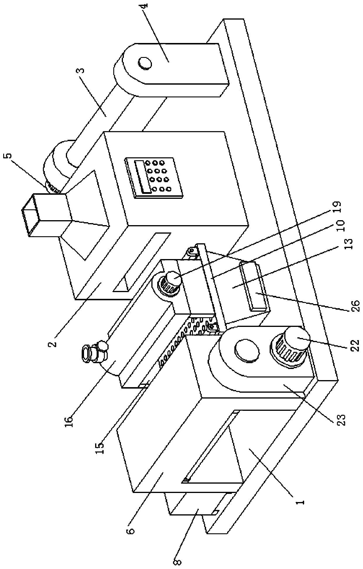
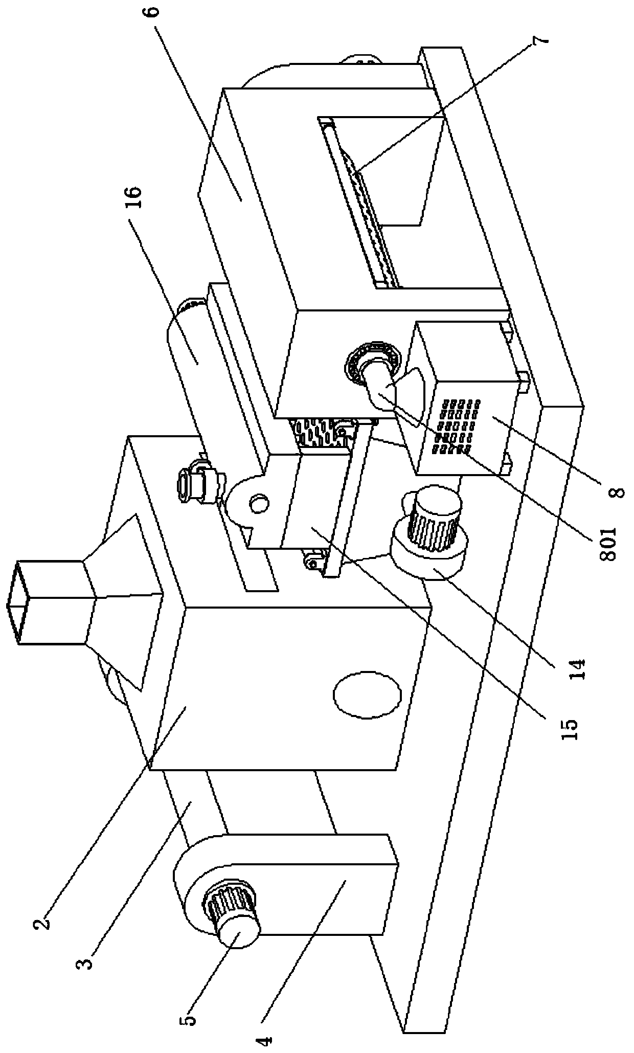
[0039] Embodiment 1 introduces an environment-friendly and high-efficiency chemical fiber fabric printing and dyeing equipment, whose main structure includes a bottom plate 1 , a drying box 2 and a winding roller 3 . Reference attached figure 1 And attached figure 2 , two rotating brackets 4 are arranged on the right end of the upper surface of the bottom plate 1, and the winding roller 3 is rotated and arranged on the two rotating brackets 4, and one of the rotating brackets 4 is provided with a winding motor 5, and the output shaft of the winding motor 5 Through the rotating bracket 4 and connected to the end face of the winding roller 3, the drying box 2 is arranged on the bottom plate 1 on the left side of the winding roller 3, and the left and right sides of the drying box 2 are respectively provided with fabric inlets (not shown in the figure). marked) and not marked in the fabric outlet drawing). Wherein, the drying box 2 is a conventional hot air drying box, and a b...
Embodiment 2
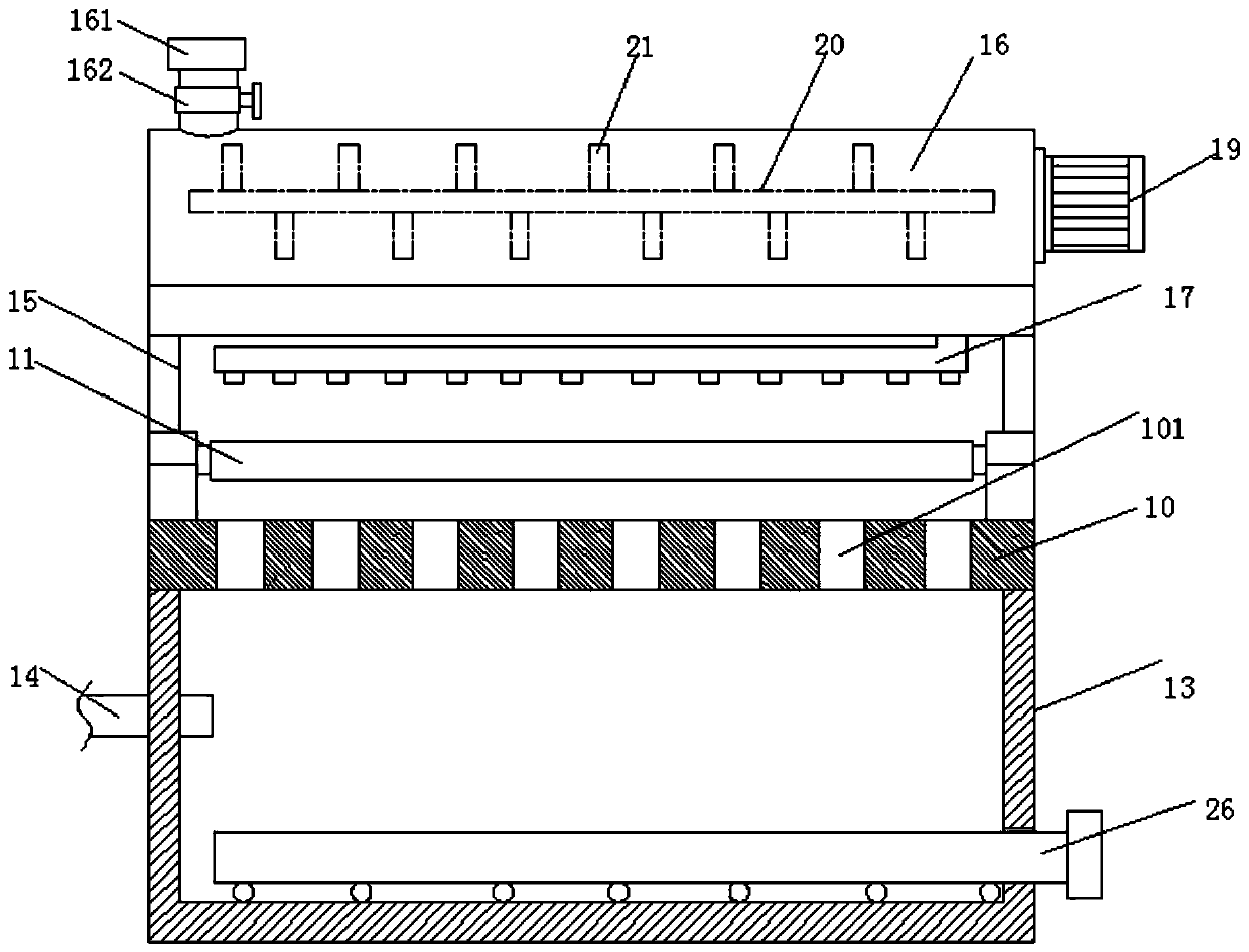
[0044] Embodiment 2 adds an energy-saving and environment-friendly steam treatment device on the basis of embodiment 1, which will be described in detail below.
[0045] Its main structure includes a bottom plate 1 , a drying box 2 and a winding roller 3 . Reference attached figure 1 And attached figure 2 , two rotating brackets 4 are arranged on the right end of the upper surface of the bottom plate 1, and the winding roller 3 is rotated and arranged on the two rotating brackets 4, and one of the rotating brackets 4 is provided with a winding motor 5, and the output shaft of the winding motor 5 Through the rotating bracket 4 and connected to the end face of the winding roller 3, the drying box 2 is arranged on the bottom plate 1 on the left side of the winding roller 3, and the left and right sides of the drying box 2 are respectively provided with fabric inlets (not shown in the figure). marked) and not marked in the fabric outlet drawing). Wherein, the drying box 2 is a...
Embodiment 3
[0051] Embodiment 3 is a further improvement made on the basis of Embodiment 2, which mainly aims at the problem of uneven dyeing caused by easy precipitation of the dye solution in the existing dye solution tank 16 , which will be specifically described below.
[0052] Its main structure includes a bottom plate 1 , a drying box 2 and a winding roller 3 . Reference attached figure 1 And attached figure 2 , two rotating brackets 4 are arranged on the right end of the upper surface of the bottom plate 1, and the winding roller 3 is rotated and arranged on the two rotating brackets 4, and one of the rotating brackets 4 is provided with a winding motor 5, and the output shaft of the winding motor 5 Through the rotating bracket 4 and connected to the end face of the winding roller 3, the drying box 2 is arranged on the bottom plate 1 on the left side of the winding roller 3, and the left and right sides of the drying box 2 are respectively provided with fabric inlets (not shown i...
PUM
 Abstract
Description
Claims
Application Information