Laser radar for long-distance detection and detection method thereof

A laser radar, long-distance technology, applied in the direction of radio wave measurement systems, instruments, etc., can solve the problem of uneven light energy of semiconductor lasers, and achieve the effects of stable rotation, easy dynamic balance, and small overall module size

Pending Publication Date: 2020-06-26
SHENZHEN KYLE OPTICS TECH CO LTD
View PDF0 Cites 5 Cited by
  • Summary
  • Abstract
  • Description
  • Claims
  • Application Information

AI Technical Summary

Problems solved by technology

The general technical solution is to couple the light energy of semiconductor lasers into multimode fibers, and achieve uniform output of light energy through mul

Method used


Image

  • Laser radar for long-distance detection and detection method thereof
  • Laser radar for long-distance detection and detection method thereof
  • Laser radar for long-distance detection and detection method thereof

Examples


Embodiment 1

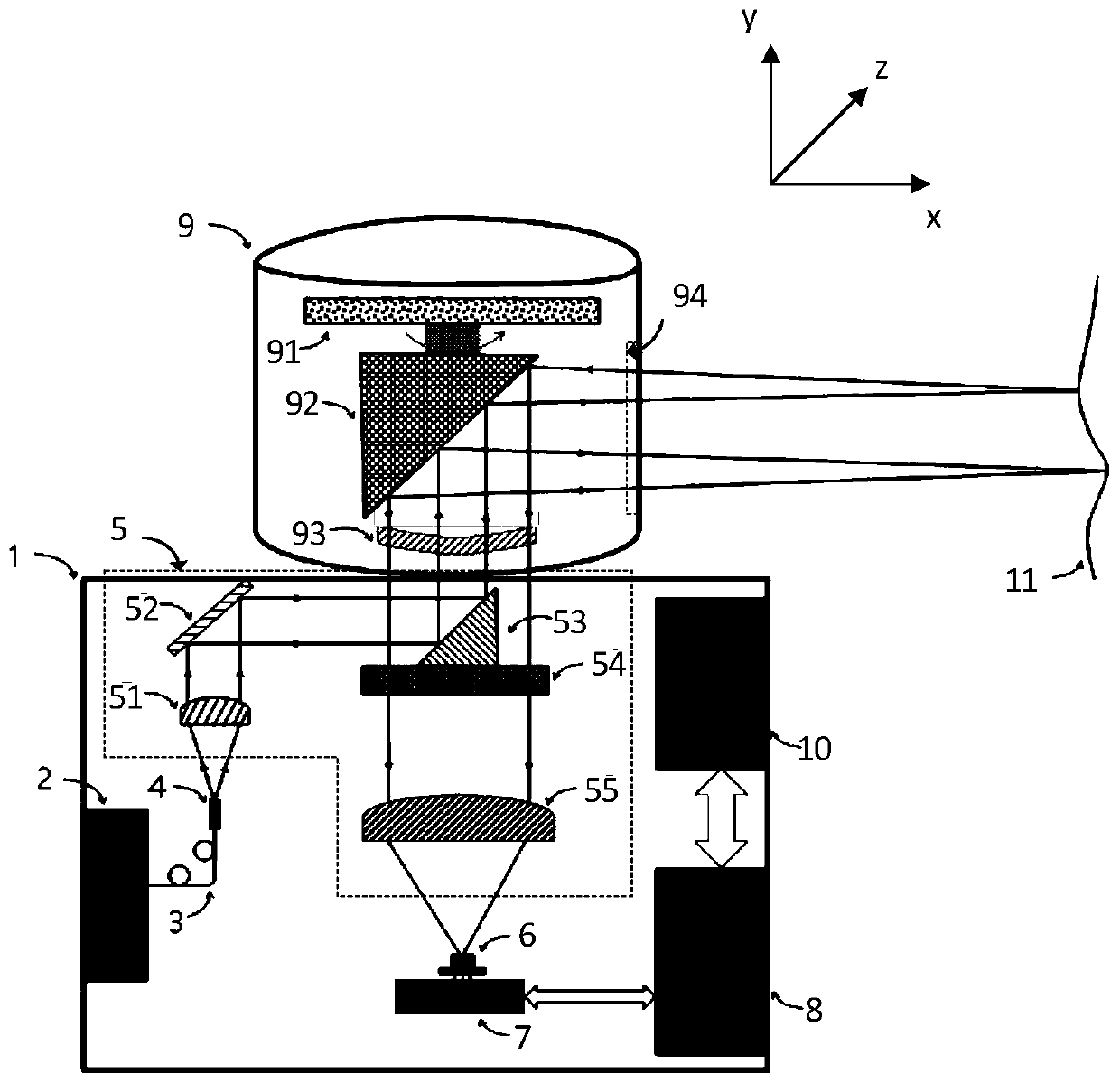
[0045]Embodiment 1 of the present invention provides a long-distance detection laser radar, such as figure 1 As shown, it includes a lidar body 1, a fiber laser 2, a single-mode fiber 3, an outgoing spot converter 4, an optical path assembly 5 in the lidar body, a receiving detector 6, and an optical path out-incident assembly 9. Specifically:

[0046] The fiber laser 2 is fixed on the inner surface of the lidar main body 1, and the fiber laser 2 transmits light energy to the outgoing spot converter 4 through the single-mode fiber 3;

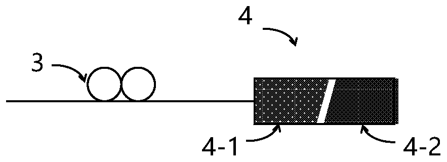
[0047] The outgoing light spot converter 4 is used to convert the outgoing light spot into a circular light spot;

[0048] The optical path assembly 5 is used to couple the outgoing light spot converter 4, the receiving detector 6 and the light path outgoing incident assembly 9, so that the outgoing light of the outgoing light spot converter 4 passes through the optical path assembly 5 and reaches the optical path outgoing incident. component 9...

Embodiment 2

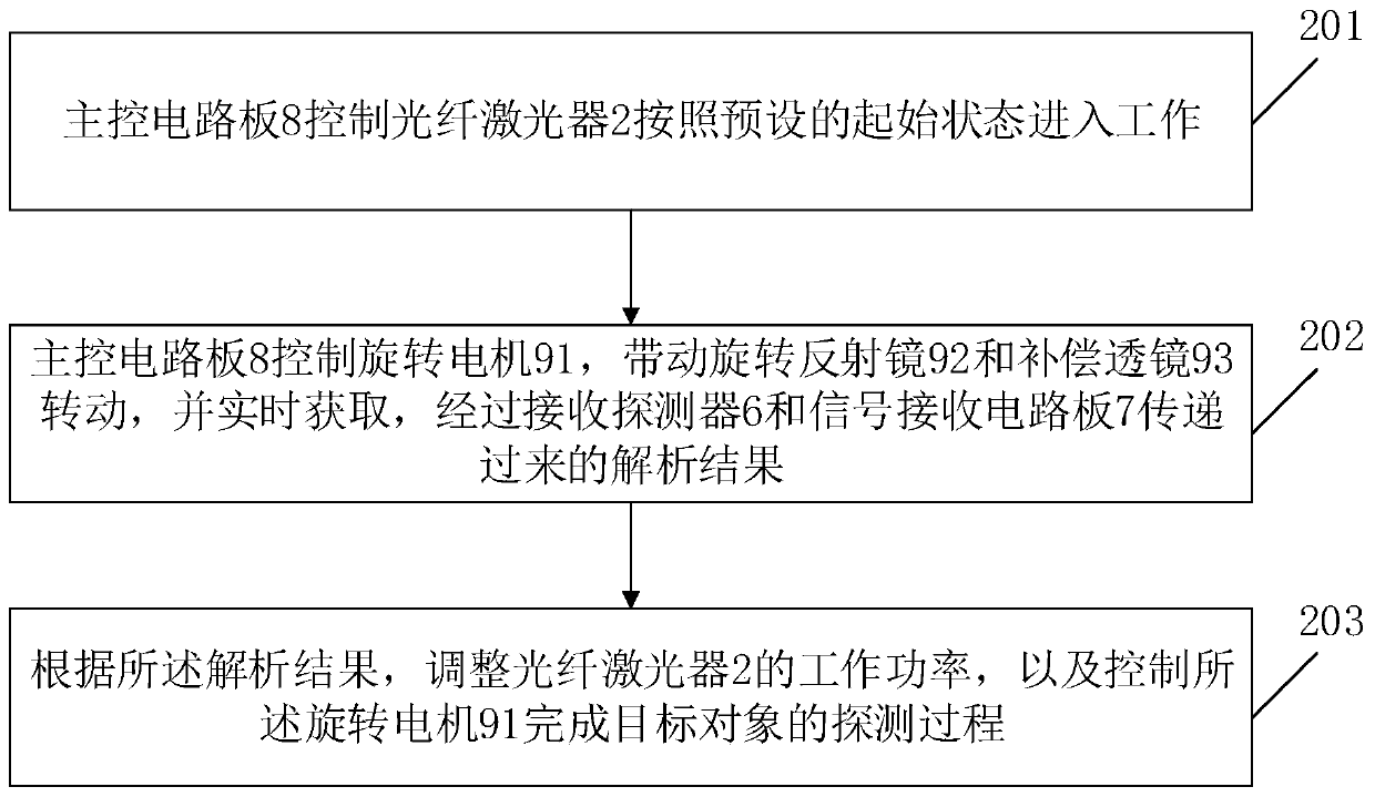
[0063] An embodiment of the present invention also provides a detection method for a long-distance detection lidar, using the long-distance detection lidar described in Embodiment 1, such as image 3 shown, methods include:

[0064] In step 201, the main control circuit board 8 controls the fiber laser 2 to work according to a preset initial state.

[0065] In step 202 , the main control circuit board 8 controls the rotating motor 91 to drive the rotating mirror 92 and the compensation lens 93 to rotate, and acquires in real time the analytical results transmitted through the receiving detector 6 and the signal receiving circuit board 7 .

[0066] In step 203, according to the analysis result, the working power of the fiber laser 2 is adjusted, and the rotating motor 91 is controlled to complete the detection process of the target object.

[0067] In the embodiment of the present invention, by adding a light spot conversion system, the elliptical light spot is converted into ...

Embodiment 3

[0070] The embodiments of the present invention will further describe the implementation mechanism of the embodiments of the present invention from the perspective of implementation principles and in combination with the specific technical solution combinations involved in Embodiment 1.

[0071] like figure 1 As shown, it is a schematic diagram of the laser radar principle based on the single-mode fiber laser of the present invention. The fiber laser 2 is fixed on the inner surface of the laser radar main body 1 by thermally conductive glue, because the fiber laser will emit a large amount of heat during high-frequency scanning operation. It needs to be fixed on the surface of the casing by thermally conductive glue, and at the same time of fixing, the heat can also be transferred to the surface of the casing. In order to improve the installation stability, the fiber laser 2 also needs to be fixed and reinforced on the inner surface of the lidar main body 1 by screws. The fib...


PUM


Abstract

The invention relates to the technical field of laser radars, and provides a laser radar for long-distance detection and a detection method thereof. An optical fiber laser 2 in the laser radar is fixed on the inner surface of a laser radar body 1, and the optical fiber laser 2 transmits optical energy to an emergent light spot converter 4 through a single-mode optical fiber 3; the emergent light spot converter 4 is used for converting an emergent light spot into a circular light spot; the light path assembly 5 is used for coupling the emergent light spot converter 4, the receiving detector 6 and the light path incident assembly 9, so that emergent light of the emergent light spot converter 4 reaches the light path incident assembly 9 through the light path assembly 5; and an optical signalreceived from the optical path incident component 9 can be transmitted to the receiving detector 6 through the optical path component 5. A light spot conversion system is added, oval light spots areconverted into circular light spots, and uniform detection in all directions of space is easy to achieve.

Description

【Technical field】 [0001] The invention relates to the technical field of laser radar, in particular to a long-distance detection laser radar and a detection method thereof. 【Background technique】 [0002] Lidar can be used to obtain 2D or 3D point cloud parameters of the target environment, and has a wide range of applications in many fields. When selecting the detection light source of the lidar, three parameters are mainly considered, namely the size of the light-emitting surface, the divergence angle of the light source and the power of the light source. At present, the detection light sources of lidar mainly include semiconductor lasers and solid-state lasers. Among them, the size of the light-emitting surface of the semiconductor laser is large, the divergence angle of the light source is also large, the power of the light source is not high, but the cost is cheap, and it is mainly used for short-range and low-cost lasers. Detection application areas. The solid-state ...

Claims


Application Information

Patent Timeline
IPC IPC(8): G01S7/481
CPCG01S7/4812G01S7/4817G01S7/4818
Inventor 张石李亚锋鲁佶
Owner SHENZHEN KYLE OPTICS TECH CO LTD
Why Eureka
Try Eureka