All-dielectric-metasurface-material-based airy beam generator

An Airy beam and metasurface technology, applied in the field of optics, can solve problems such as unfavorable applications of optical systems, and achieve the effects of low cost, simple structure and small volume

Pending Publication Date: 2020-06-26
ZHEJIANG UNIVERSITY OF SCIENCE AND TECHNOLOGY
View PDF5 Cites 6 Cited by
  • Summary
  • Abstract
  • Description
  • Claims
  • Application Information

AI Technical Summary

Problems solved by technology

[0003] Usually, an Airy beam is Fourier transformed by a beam of Gaussian light, which is generated by an optical system composed of a spatial ligh

Method used


Image

  • All-dielectric-metasurface-material-based airy beam generator
  • All-dielectric-metasurface-material-based airy beam generator
  • All-dielectric-metasurface-material-based airy beam generator

Examples


Embodiment 1

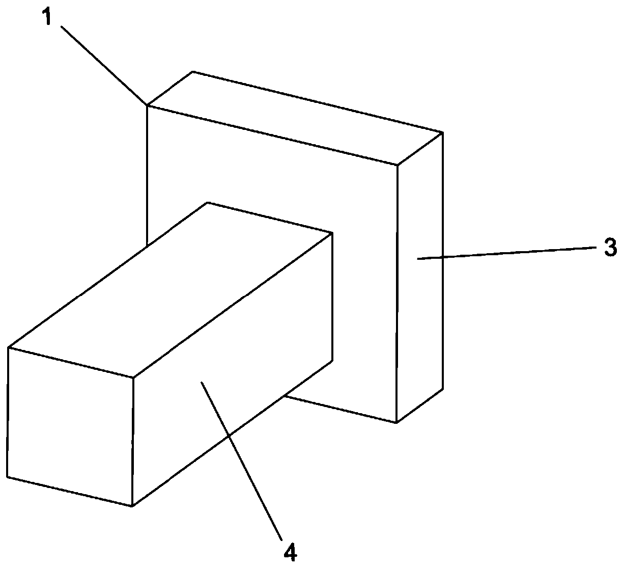
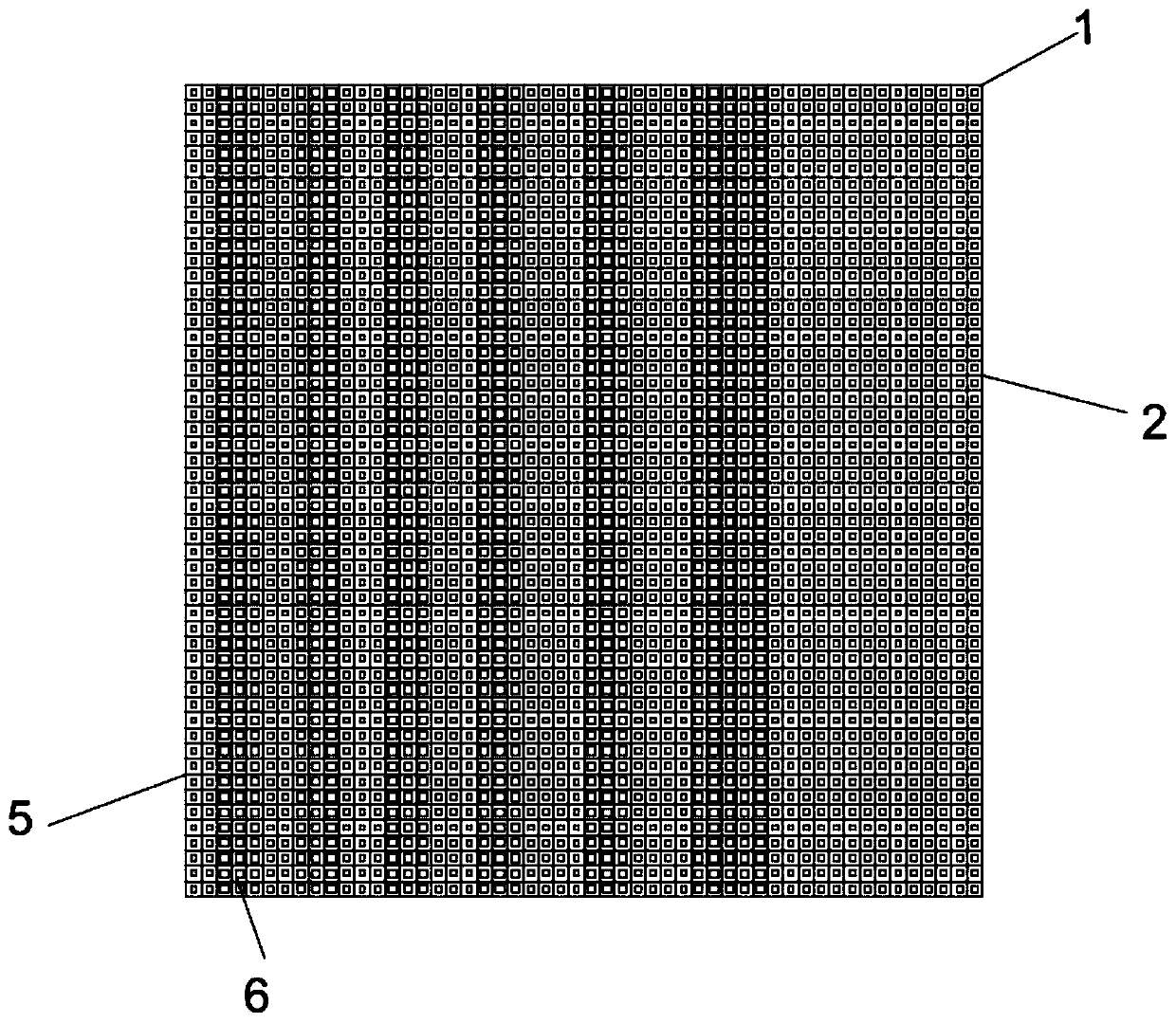
[0035] Embodiment 1: An Airy beam generator based on an all-dielectric metasurface material, the Airy beam generator is composed of 44×44 periodic units 1 arranged to form a square array phase plate 2; the periodic unit 1 includes a substrate layer 3 , the substrate layer 3 is a column with a square cross-section, the width of the substrate layer 3 is 450nm, the material of the substrate layer 3 is silicon dioxide, and the substrate layer 3 is provided with a square nano-column 4 with a square cross-section. The material of the nanocolumn 4 is titanium dioxide, and the height of the nanocolumn 4 is 500nm; when the transmitted light passes through the array phase plate 2, the periodic unit 1 with a phase difference of 0 is the first array block 5, and when the transmitted light passes through the array phase plate 2 The periodic unit 1 whose phase difference is π is the second array block 6; the width of the nano-column 4 in the first array block 2 is 140nm; the width of the nan...

Embodiment 2

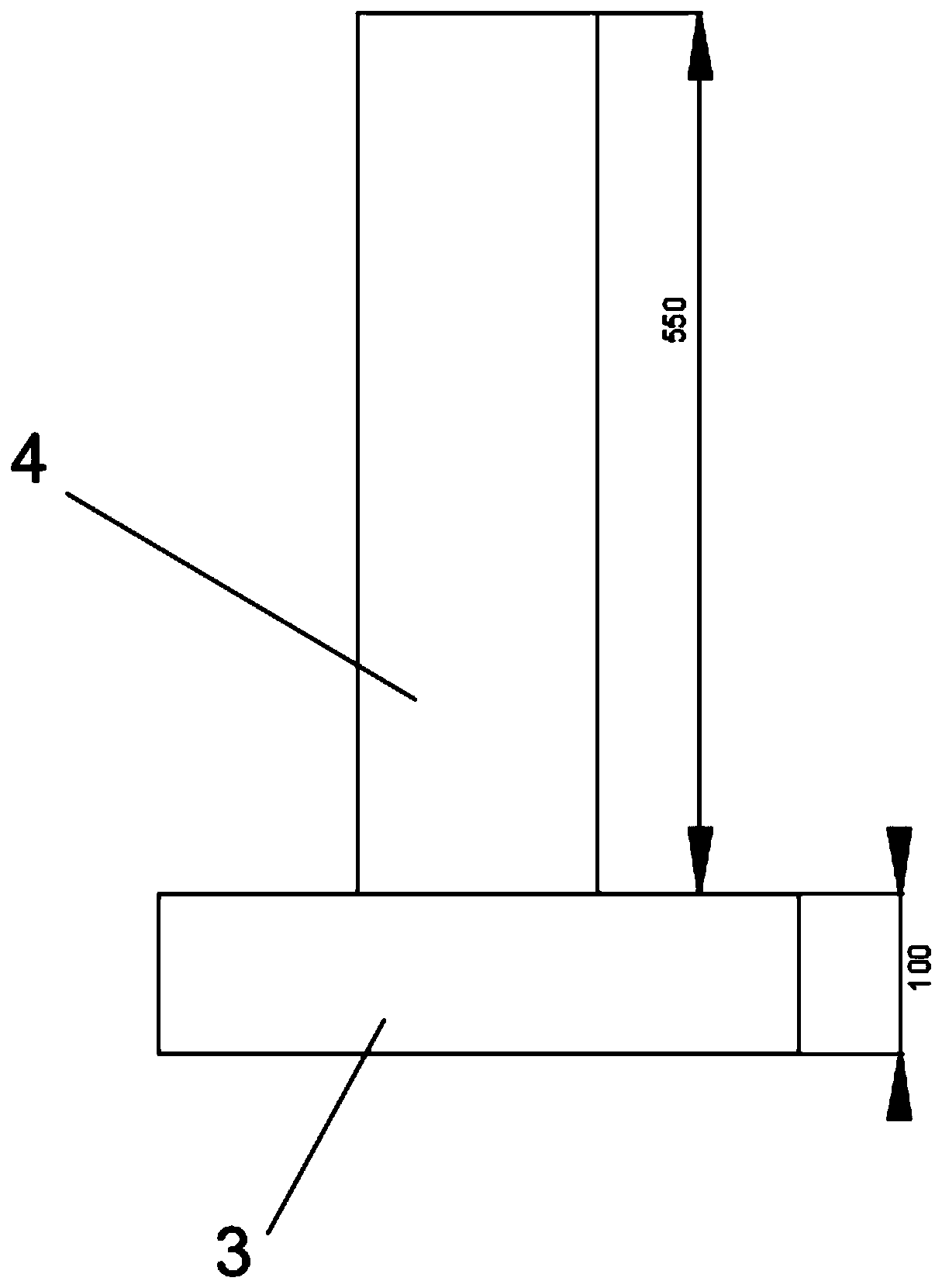
[0043] Embodiment 2: Airy beam generator based on all-dielectric metasurface material, such as Figure 1-5 As shown, the Airy beam generator is composed of 53×53 periodic units 1 arranged to form a square array phase plate 2; the periodic unit 1 includes a substrate layer 3, and the substrate layer 3 is a cylinder with a square cross section. The width of the substrate layer 3 is 400nm, the material of the substrate layer 3 is silicon dioxide, the substrate layer 3 is provided with a square nano-column 4, the material of the nano-column 4 is titanium dioxide, the nano-column 4 The height is 550nm; if figure 2 and Image 6 As shown, when the transmitted light passes through the array phase plate 2, the periodic unit 1 with a phase difference of 0 is the first array block 5, and when the transmitted light passes through the array phase plate 2, the periodic unit 1 with a phase difference of π is the second array Block 6; the width of the nanocolumn 4 in the first array block ...


PUM

PropertyMeasurementUnit
Widthaaaaaaaaaa
Heightaaaaaaaaaa
Widthaaaaaaaaaa

Abstract

The invention discloses an all-dielectric-metasurface-material-based Airy beam generator. The Airy beam generator is a square array phase plate formed by arranging a plurality of periodic units. Eachperiodic unit comprises a substrate layer, and the substrate layer is provided with a nano column with a square section; when transmission light passes through the array phase plate, the obtained periodic unit with the phase difference of 0 is a first array block, and when the transmission light passes through the array phase plate, the obtained periodic unit with the phase difference of pai is asecond array block. In the array phase plate, in the x-axis direction, when an initial wave packet phi of the Airy beam is larger than 0, the periodic units in the same column select the first array block, and when the initial wave packet phi of the Airy beam is smaller than 0, the periodic units in the same column select the second array block. The Airy beam can be simply and conveniently generated without a complex optical system, and the Airy beam generator has the advantages of being small in size, simple in structure and low in cost.

Description

technical field [0001] The invention relates to an Airy beam generator based on an all-dielectric metasurface material, belonging to the field of optics. Background technique [0002] The Airy beam was first proposed by Berry and Balazs in the field of quantum mechanics. It has the characteristics of no diffraction and self-healing. In addition, the characteristic of self-acceleration along the curved trajectory makes it have unique advantages in many fields. In 2007, Siviloglou et al. combined the Schrödinger equation and the paraxial Helmholtz equation to introduce it into the field of optics so that it could be successfully prepared. [0003] Usually, an Airy beam is Fourier-transformed by a beam of Gaussian light, which is generated by an optical system composed of a spatial light modulator and a lens. The complex optical system is not conducive to the application in highly compact and integrated modern application devices. With the rise of metasurfaces, more and more p...

Claims


Application Information

Patent Timeline
IPC IPC(8): G02B27/09G02B5/30
CPCG02B5/3083G02B27/0938
Inventor 徐弼军吴白瑞
Owner ZHEJIANG UNIVERSITY OF SCIENCE AND TECHNOLOGY
Why Eureka
Try Eureka