
Rapid coconut peeling device

A fast, coconut technology, applied in the fields of shelling, pod removal, food science, etc., can solve the problems of unsightly peeling, low peeling efficiency, low manual peeling efficiency, etc., to speed up peeling efficiency and reduce labor. Powerful, easy-to-use effects

Inactive Publication Date: 2020-06-30
黄小马
View PDF0 Cites 5 Cited by
  • Summary
  • Abstract
  • Description
  • Claims
  • Application Information

AI Technical Summary

Problems solved by technology

[0004] In order to overcome the existing need for professional people to peel the coconut surface, even so, it is very laborious to manually remove the coconut skin, and the manual peeling efficiency of people who have not undergone a large number of coconut peeling operations low, and the peeling is not beautiful. The existing peeling equipment has low peeling efficiency and cannot meet the shortcomings of peeling coconuts of different sizes. Coconut quick peeling device with high peeling efficiency

Method used


Image

  • Rapid coconut peeling device
  • Rapid coconut peeling device
  • Rapid coconut peeling device

Examples


Embodiment 1

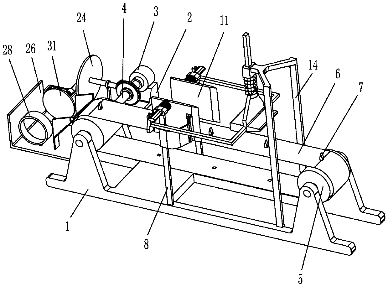
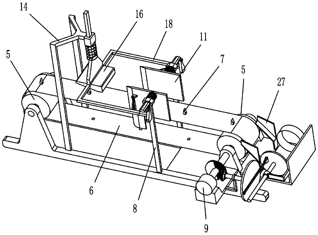
[0019] A quick coconut peeling device, such as Figure 1-5 As shown, it includes support 1, support base 2, motor 3, power shaft 4, transmission wheel 5, power belt 6, pin 7, second baffle plate 26, inclined plate 27, circular cutter 28, fixed plate 29 , a second guide sleeve 30, a guide rod 31, a push plate 32, a cutting device, a transmission device and a material retaining device, the support base 2 is fixedly installed on the left side of the support 1, and the motor 3 is fixedly installed on the support On the seat 2, one of the power shafts 4 is installed on the output shaft of the motor 3, the other power shaft 4 is installed on the right side of the support 1 through a bearing, and the two transmission wheels 5 are respectively installed on the two power shafts 4 And there is a power belt 6 connected therebetween, the pins 7 that can fix the coconut are installed on the power belt 6 at intervals, and the second baffle plate 26 is fixedly installed on the left side of t...

Embodiment 2

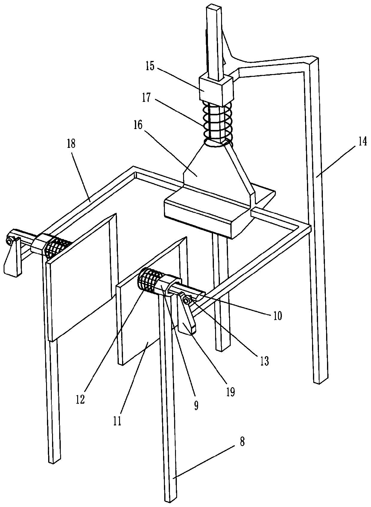
[0021] On the basis of Example 1, such as Figure 1-5 As shown, the cutting device includes a first pole 8, a first guide sleeve 9, a slide bar 10, a cutting knife 11, a return spring 12, a roller 13, a fixed rod 14, a sliding sleeve 15, and an extruding rod 16 , the first return spring 17, the first connecting rod 18 and the wedge block 19, the first pole 8 is fixedly installed on the support 1 by welding, and the two first guide sleeves 9 are fixedly installed on the two second The upper end of a rod 8, the slide bar 10 is slidably installed on the first guide sleeve 9 and the slide bar 10 can move back and forth along the first guide sleeve 9, and the cutting knife 11 is fixedly installed on the slide by welding. One end of the rod 10, one end of the return spring 12 is installed on the cutting knife 11, the other end is installed on the first guide sleeve 9 and passed by the slide bar 10, and the roller 13 is rotatably installed on the slide bar 10, so The fixed rod 14 is...


PUM


Abstract

The invention relates to the field of coconut processing, specifically to a rapid coconut peeling device. The objective of the invention is to provide the rapid coconut peeling device which can comprehensively peel coconuts and is high in peeling efficiency. According to a technical scheme of the invention, the rapid coconut peeling device comprises a support base, a supporting seat, a motor, power rotating shafts, transmission wheels, a power belt, pins, a second baffle plate, an inclined plate, a circular cutter, a fixed plate, a second guide sleeve and the like, wherein the supporting seatis arranged on the support base; the motor is arranged on the supporting seat; one power rotating shaft is arranged on the output shaft of the motor; and the other power rotating shaft is arranged onthe support base through a bearing. The rapid coconut peeling device provided by the invention has the following advantages: operation is simple; and a worker only needs to start the motor to fix coconuts to the power belt one by one, and the coconuts can be comprehensively peeled, so the labor intensity of the worker is reduced.

Description

technical field [0001] The invention relates to the field of coconut treatment, in particular to a quick coconut peeling device. Background technique [0002] Coconut, a plant of the genus Coconut in the family Palmaceae. The plant is tall, tree-like, 15-30 meters high, the stem is thick, with ring-shaped leaf scars, the base is thickened, often clustered with small roots, the petiole is thick, the inflorescence is axillary, the fruit is ovoid or nearly Spherical, the fruit cavity contains endosperm, embryo and juice, and the flowering and fruiting period is mainly in autumn. [0003] When people need to eat the coconut meat in the coconut or drink the coconut juice in the coconut, they need to cut off the two ends of the coconut, then remove the skin on the outer surface of the coconut, and then open the coconut for consumption. Because the outer surface of the coconut is relatively hard, Difficult to handle, requires professional people to peel the coconut surface. Even s...

Claims


Application Information

Patent Timeline
Patent Type & Authority Applications(China)
IPC IPC(8): A23N5/08
CPCA23N5/08
Inventor 黄小马
Owner 黄小马
Learn More