Rolling connection forming tool of pipe joint based on high filling rate and rolling connection process

A technology for forming tooling and pipe joints. It is used in feeding devices, positioning devices, storage devices, etc., which can solve the problems of pipe breakage or oil leakage, failure to seal, oil leakage, etc., so as to increase the service life and ensure slow The effect of improving the quality of rolling

Active Publication Date: 2020-06-30
DALIAN CANDL TECH DEV CO LTD +1
View PDF5 Cites 2 Cited by
  • Summary
  • Abstract
  • Description
  • Claims
  • Application Information

AI Technical Summary

Problems solved by technology

[0005] 1. The filling rate of rolling is insufficient, and the maximum effective rolling area and the appropriate gradient of the plastic deformation and thinning of the wall thickness of the conduit cannot be achieved. The compressive stress on the inner surface of the conduit and the contact stress on the outer surface are insufficient, resulting in unqualified bending fatigue performance
[0006] 2. The filling rate of rolling is insufficient, and it is obvious that the combination with the pipe joint is not tight, that is, the contact stress between the outer wall of the conduit and the pipe joint is insufficient, and the sealing effect cannot be achieved, and oil will leak, resulting in unqualified airtight and pressure resistance performance
[0007] 3. The filling rate of rolling is insufficient, and the material of the conduit in the groove of the pipe joint is less filled. When the pipe is stretched axially, the axial resistance is small, and the conduit will break or leak oil, resulting in unqualified connection strength performance

Method used


Image

  • Rolling connection forming tool of pipe joint based on high filling rate and rolling connection process
  • Rolling connection forming tool of pipe joint based on high filling rate and rolling connection process
  • Rolling connection forming tool of pipe joint based on high filling rate and rolling connection process

Examples


Embodiment 1

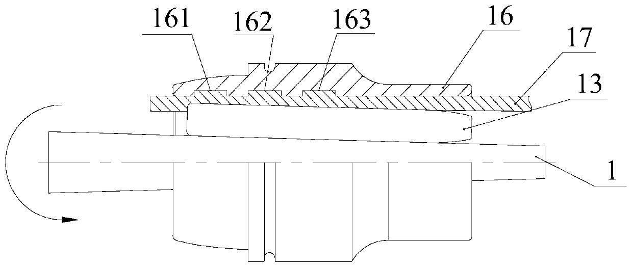
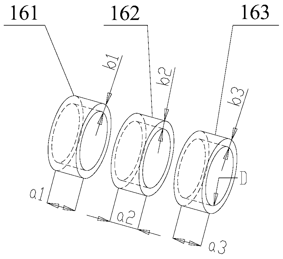
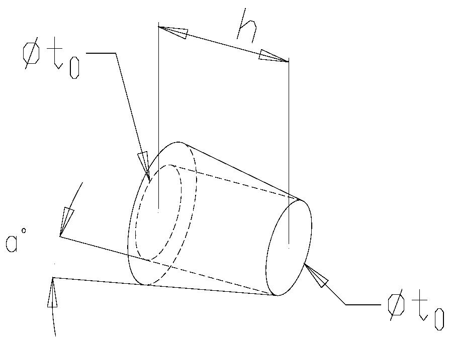
[0091] The filling volume of pipe joint groove material V=π*a1*b1*(D+b1)+π*a2*b2*(D+b2)+π*a3*b3*(D+b3); the pressure of conduit material Inlet volume W=π*D*h*sinα(D+h*sinα) / 2, in accordance with the requirements of the taper and thinning rate of the working end of the mandrel 1, make W>V, select a suitable t f make shear thinning ф t Between 15% and 40%, in order to obtain the maximum rolling area and meet the requirements of high filling rate, h (the effective length of the needle) is approximately equal to the length of the pipe joint, and the diameter of the needle is approximately equal to t 0 / 3, mandrel taper is 2α. The above rolling forming process can provide a theoretical basis for rolling processing and optimize process parameters.

[0092] The material of pipe sleeve 16 is stainless steel 15-5PH, and the material of metal conduit 17 is titanium alloy Ti-3Al-2.5V, and roll forming is carried out. The relevant material parameters of pipe sleeve 16 and metal conduit ...


PUM


Abstract

The invention provides a rolling connection forming tool of a pipe joint based on a high filling rate and a rolling connection process. The tool comprises an inner diameter expander and a clamping die. The tool is characterized in that a mandrel arranged in a mandrel cover in a sleeved manner and used for implementing rolling rotation in the inner diameter expander is of a spilt structure which isdivided into a working end and a non-working end; the working end is a part inserted into a metal guide pipe for implementing rolling rotation of the mandrel matched with the mandrel cover, is of a cone structure, and the outer diameter of the working end tends to decrease gradually in a direction pointed to insertion; and the taper of the working end of the mandrel meets a certain relational expression. The rolling process is that a high hardness smooth roller pin is in contact with the inner wall of the metal guide pipe by the tool, so that local plastic deformation occurs in a surface layer of the metal guide pipe to generate surface pressure stress, and a pipe wall material is rolled into the pipe joint with a groove to achieve rolling connection. The rolling connection forming tool has the advantages of reasonable structural design, improved performance of a rolled product, high percent of pass and the like.

Description

technical field [0001] The invention relates to the technical field of pipe forming processing equipment, in particular to a high filling rate pipe joint rolling connection forming tool and rolling connection process. Background technique [0002] At present, the connection methods of aircraft ducts are mainly flared connection and rolling connection. Due to the large sealing surface area of ​​the flared connection, it is difficult to eliminate the shape error and surface roughness error generated in the manufacturing process, and the sealing performance is not good. Good, poor self-locking, usually the fuse is locked, which greatly increases the weight of the aircraft. In contrast, the rolling joining process has certain advantages. [0003] The rolling connection process has the characteristics of high sealing, light weight, shockproof self-locking, no insurance, and convenient maintenance. It has been widely used in foreign aircraft. It is a mature and reliable connectio...

Claims


Application Information

Patent Timeline
Patent Type & Authority Applications(China)
IPC IPC(8): B21D39/04B21D43/00
CPCB21D39/046B21D43/003
Inventor 林宏伟朱必多刘维亮
Owner DALIAN CANDL TECH DEV CO LTD
Why Eureka
Try Eureka