Coalescence degreaser for oilfield sewage treatment

A coalescing degreaser and oilfield sewage technology, applied in water/sewage multi-stage treatment, water/sludge/sewage treatment, mining wastewater treatment, etc., can solve the problem of ineffective implementation of anti-corrosion methods, corrosion of equipment body and internal components , stable operation, adverse effects and other issues, to ensure long-term safe and effective operation, improve sewage treatment capacity, and excellent mechanical and physical properties

Active Publication Date: 2020-06-30
SHENGLI OIL FIELD XINDA PIPE IND TECH DEV CO LTD
View PDF10 Cites 8 Cited by
  • Summary
  • Abstract
  • Description
  • Claims
  • Application Information

AI Technical Summary

Problems solved by technology

[0003] Traditional oil-water separation treatment equipment is basically made of metal materials, with poor corrosion resistance and serious corrosion, especially for small pressure separation equipment (three-phase separator, coalescing degreaser, filter) due to its small internal space and The components are complex, and the traditional anti-corrosion methods cannot be effectively implemented. Up to now, no effective way to control corrosion has been found. The equipment body and internal components are severely corroded, with short service life and high maintenance costs, which have brought great impact on the smooth operation of the entire oil-water treatment system and HSE management. Negative Effects
That is to say, the metal coalescing degreaser that has been used so far has great limitations in terms of corrosion resistance

Method used


Image

  • Coalescence degreaser for oilfield sewage treatment
  • Coalescence degreaser for oilfield sewage treatment
  • Coalescence degreaser for oilfield sewage treatment

Examples


Embodiment 1

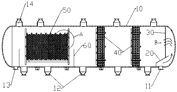
[0066] Such as figure 1 As shown, a coalescence degreaser for oilfield sewage treatment provided in this embodiment includes: a tank body 10; inside the tank body 10, a flow stabilization device 20, a rectification device 30, a primary filtration Device 40 and oil gathering device 50. The bottom of the right end of the tank body 10 is provided with a medium inlet 11, the top of the tank body 10 is provided with one or several oil collecting ports 14, and the bottom of the other end of the tank body 10 is provided with a drain port 13; the bottom of the tank body 10 Several mud outlets 12 are arranged at intermediate intervals. Several fenders 60 are also arranged at intervals in the tank body 10 to prevent the silt from continuing to flow. Generally, the fenders 60 are arranged on one side of the downstream direction of the water flow at the mud discharge port 12, thereby guiding the silt through the discharge. Mud discharge.

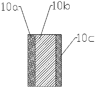
[0067] Such as figure 2 As shown, the tank b...

Embodiment 2

[0082] The structure of this embodiment is basically the same as that of Embodiment 1, the difference is that:

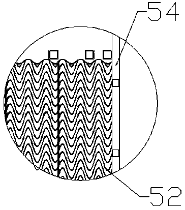
[0083] Such as Figure 7 As shown, the oil gathering device provided in this embodiment includes: a coalescing and separating corrugated plate 52 and a support member 51; a plurality of the coalescing and separating corrugated plates 52 are arranged at intervals up and down, and two adjacent coalescing and separating corrugated plates A wave-shaped water flow channel 53 is formed between 52; the support member 51 is erected in the water flow channel 53, and its two ends are fixedly connected with two adjacent coalescing and separating corrugated plates 52 up and down.

[0084] The present invention increases the cross-sectional area of ​​the water flow channel 53 between adjacent corrugated plates by thinning the thickness of the corrugated plates in the prior art, thereby greatly improving the sewage treatment capacity; and under the premise that the sewage treatment...

Embodiment 3

[0095] The structure of this embodiment is basically the same as that of Embodiment 2, the difference is that:

[0096] Such as Figure 10 As shown, when the coalescing and separating corrugated plate 52 is relatively thin, for example, when the thickness is less than 5mm, the easier way to arrange the support member 51 is: the top and bottom of the coalescing and separating corrugated plate 52 are respectively provided with installation protrusions and insertion groove, the installation protrusion and the insertion groove can be formed synchronously when the coalescing and separation corrugated plate 52 is laminated; the support member 51 is a truncated cone, and the bottom of the support member 51 is set to be inserted into the installation protrusion The connection hole, the top of the support member 51 is provided with a clip joint inserted into the insertion slot.

[0097] The supporting member 51 is generally in the shape of a truncated cone. When the sewage flows thro...


PUM


Abstract

The invention provides a coalescence degreaser for oilfield sewage treatment. The coalescence degreaser comprises a tank body, a flow stabilizing device, a rectifying device, a primary filtering device and an oil gathering device; the tank body sequentially comprises a lining layer formed by jet yarns in a jet molding mode, a structural layer formed by resin and fiber material composite materialsin an enveloping and winding mode and an outer surface layer formed by gel coat resin in a spraying mode from inside to outside in the thickness direction of the tank wall. The oil gathering device comprises a coalescence separation corrugated plate and a supporting piece. The thickness of corrugated plates in the prior art is reduced to increase the cross sectional area of a water flow channel between the adjacent corrugated plates, so that the sewage treatment capacity is greatly improved; and on the premise that the sewage treatment efficiency is not reduced, namely, the cross section of the water flow channel is kept unchanged, the arrangement number of the corrugated plates is greatly increased, so that the contact area of the corrugated plates and sewage is increased, and the oil gathering efficiency and effect are improved.

Description

technical field [0001] The invention belongs to the technical field of pressure separation treatment equipment for oil fields, and in particular relates to a coalescence degreaser for oil field sewage treatment. Background technique [0002] At present, most domestic old oilfields have entered the development period of ultra-high water cut. With the adoption of development techniques such as water flooding, polymer flooding, ASP flooding, heavy oil recovery, and gas flooding, the produced water in oilfields has various water types and complex water properties. Corrosive characteristics. [0003] Traditional oil-water separation treatment equipment is basically made of metal materials, with poor corrosion resistance and serious corrosion, especially for small pressure separation equipment (three-phase separator, coalescing degreaser, filter) due to its small internal space and The components are complex, and the traditional anti-corrosion methods cannot be effectively implem...

Claims


Application Information

Patent Timeline
Patent Type & Authority Applications(China)
IPC IPC(8): C02F9/02C02F103/10
CPCC02F1/001C02F1/40C02F2103/10Y02A20/204
Inventor 吴永太陶佳栋武飞卢明昌曹付军吴少林
Owner SHENGLI OIL FIELD XINDA PIPE IND TECH DEV CO LTD
Why Eureka
Try Eureka