full combustion gasifier

A technology of sufficient combustion and gasification furnace, which is applied in the direction of combustion equipment, combustion method, furnace/stove with hot water device, etc., can solve the problems of insufficient combustion of biofuels, etc., and achieve the goal of improving sufficiency and dispersion Effect

Active Publication Date: 2021-11-19
韶关市海粤农业发展有限公司
View PDF0 Cites 0 Cited by
  • Summary
  • Abstract
  • Description
  • Claims
  • Application Information

AI Technical Summary

Problems solved by technology

[0005] The purpose of the present invention is to solve the problem of insufficient combustion of biomass fuel for heating, and the gasifier with sufficient combustion proposed

Method used


Image

  • full combustion gasifier
  • full combustion gasifier
  • full combustion gasifier

Examples


Embodiment 1

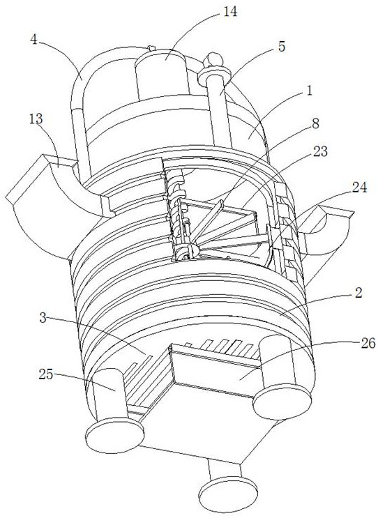
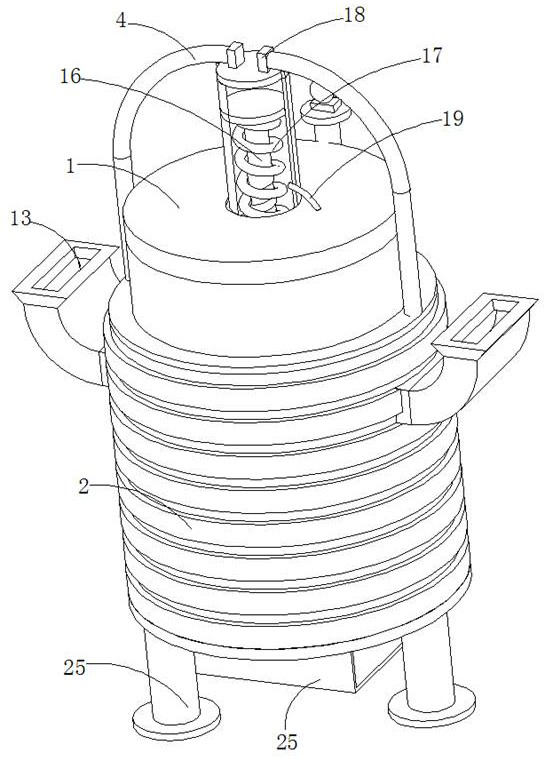
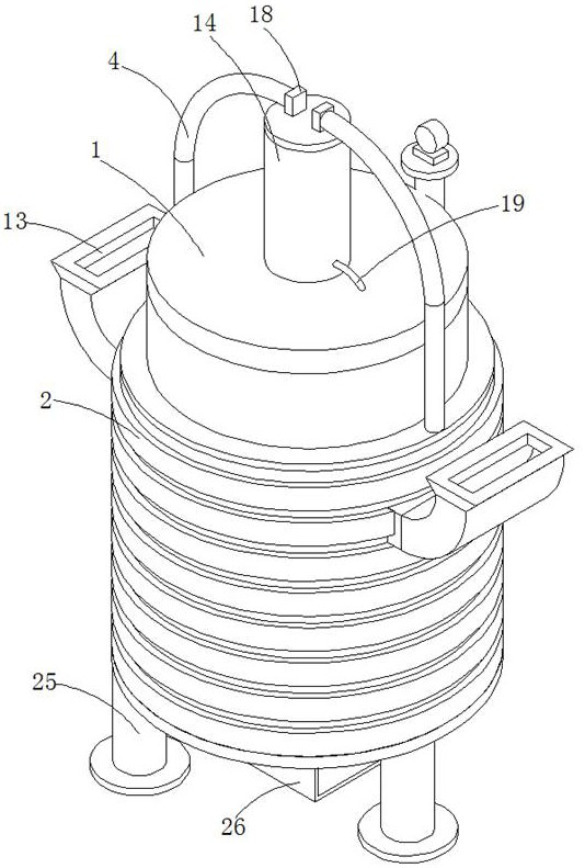
[0031] refer to Figure 1-5 , a fully combusted gasifier, comprising a furnace body 1 and a heat preservation shell 2, a water storage layer is arranged between the furnace body 1 and the heat preservation shell 2, a fire grate 3 is fixedly connected to the bottom of the furnace body 1, and the heat preservation shell 2 The top is connected with the steam generation pipe 4 and the heat supply pipe 5 which are connected with the aquifer, and the end of the steam generation pipe 4 away from the insulation shell 2 is connected with a lifting mechanism placed on the top of the furnace body 1, and the movable end of the lifting mechanism is connected with a Place the screw mandrel 6 in the furnace body 1, the outer wall of the screw mandrel 6 is fixedly connected with the first fluffy frame 8 through the fixing ring 7, and the outer wall of the screw mandrel 6 is also slidably connected with the second fluffy frame 8 placed below the first The fluffy frame 9 is slidably connected w...

Embodiment 2

[0040] refer to Figure 1-3 , a fully combusted gasifier, which is basically the same as in Embodiment 1, furthermore, the end of the pressure relief pipe 19 away from the cylinder body 14 is placed in the furnace body 1;

[0041] The steam enters the furnace body 1 to provide oxygen for the further combustion of the fuel and the flue gas produced by fuel combustion, further improving the adequacy of fuel combustion.

Embodiment 3

[0043] refer to Figure 1-5 , the fully combusted gasifier is basically the same as in Example 1, and furthermore, the outer wall of the screw rod 6 between the fixed ring 7 and the lifting mechanism is also fixedly connected with a U-shaped frame 23, and the vertical position of the U-shaped frame 23 The section is connected with a baffle plate 24, and the baffle plate 24 matches with the feed port on the feed bin 13;

[0044] The water in the aquifer is gradually heated until it boils, and then the steam flows from the aquifer to the steam generating pipe 4, and the steam flowing to the steam generating pipe 4 flows into the cylinder 14 through the intake valve 18, and flows into the cylinder 14 The amount of steam increases, the piston 15 drives the transmission rod 16 to squeeze the return spring 17, and as the return spring 17 continues to tighten, the transmission rod 16 drives the screw rod 6 to move down, driving the U-shaped frame 23 to move down, and at this time the...


PUM


Abstract

The invention discloses a gasification furnace with sufficient combustion, which belongs to the technical field of gasification furnaces; the gasification furnace with sufficient combustion includes a furnace body and a heat preservation shell, a water storage layer is arranged between the furnace body and the heat preservation shell, and the bottom of the furnace body is fixed A fire grate is connected, and the top of the insulation shell is connected with a steam generation pipe and a heat supply pipe connected with the water storage layer. The end of the steam generation pipe far away from the insulation shell is connected with a lifting mechanism placed on the top of the furnace body, and the movable end of the lifting mechanism is movable. The end is connected with a screw rod placed in the furnace body, the outer wall of the screw rod is fixedly connected with the first fluffy frame through the fixing ring, and the outer wall of the screw rod is also slidably connected with the second fluffy frame placed below the first fluffy frame, the fixing ring The upper slide is connected with a pull rod, and one end of the pull rod passing through the fixed ring is fixedly connected with the second fluffy frame, and the inner wall of the furnace body close to the fire grate is fixedly connected with a positioning ring; the invention avoids accumulation of fuel during combustion and untimely cleaning of furnace ash problem, improving combustion efficiency.

Description

technical field [0001] The invention relates to the technical field of gasification furnaces, in particular to a gasification furnace with sufficient combustion. Background technique [0002] The current situation is: on the one hand, the prices of non-renewable resources such as coal, oil and natural gas continue to rise due to shortages; on the other hand, a large amount of available bio-energy is wasted. Not limited to, such as rice bran, rice straw, wheat straw, rice straw, sorghum straw and wood chips, etc., especially in rural areas, people will see farmers burning rice straw, wheat straw, rapeseed straw, etc. directly in the field from time to time , which not only affects the environment, but also wastes resources. [0003] The gasification furnace in the prior art cannot be stirred or turned during the combustion process of the biofuel, resulting in relatively dense fuel and poor air circulation, resulting in insufficient combustion of the fuel, and the combustion ...

Claims


Application Information

Patent Timeline
Patent Type & Authority Patents(China)
IPC IPC(8): F24B1/183F24B1/191F24B7/00F24B13/02F24D15/02F23L7/00
CPCF23L7/005F24B1/183F24B1/1915F24B7/00F24B13/02F24D15/02
Inventor 梁灼林梁赐鸿朴桂林傅健武强廖珍连谢路群
Owner 韶关市海粤农业发展有限公司
Why Eureka
Try Eureka