Side pump signal beam combiner for realizing flat-topped light beam and preparation method thereof

A flat-top beam and beam combiner technology, which is applied in the directions of light guides, optics, instruments, etc., can solve the problems of non-universality of incident light, high process and cost, and no requirements for beam energy distribution, and achieve easy all-fiberization. Integrated, short production cycle, wide range of effects

Active Publication Date: 2020-06-30
江苏睿赛光电科技有限公司
View PDF7 Cites 4 Cited by
  • Summary
  • Abstract
  • Description
  • Claims
  • Application Information

AI Technical Summary

Problems solved by technology

However, after different modes of light are introduced into the optical fiber, a specific refractive index distribution is required to obtain a flat-topped spot energy distribution. The same optical fiber is not universal for different incident lights. In addition, a specific refractive index distribution can be prepared without continuous change. optical fiber preform rod, the required process and cost are relatively high
[0009] At present, the fiber side coupling scheme has been proposed, but it is currently used for the pump light transmission in the fiber laser, the signal light is transmitted in the main signal fiber, the pump light is transmitted in the side arm input fiber, and the opposite side arm enters the main signal fiber. The beam energy distribution of the signal fiber is not required

Method used


Image

  • Side pump signal beam combiner for realizing flat-topped light beam and preparation method thereof
  • Side pump signal beam combiner for realizing flat-topped light beam and preparation method thereof
  • Side pump signal beam combiner for realizing flat-topped light beam and preparation method thereof

Examples


Embodiment 1

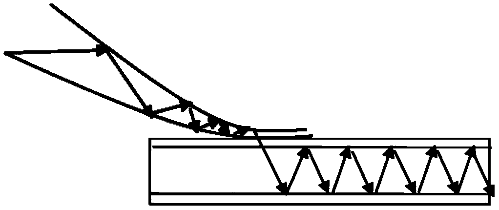
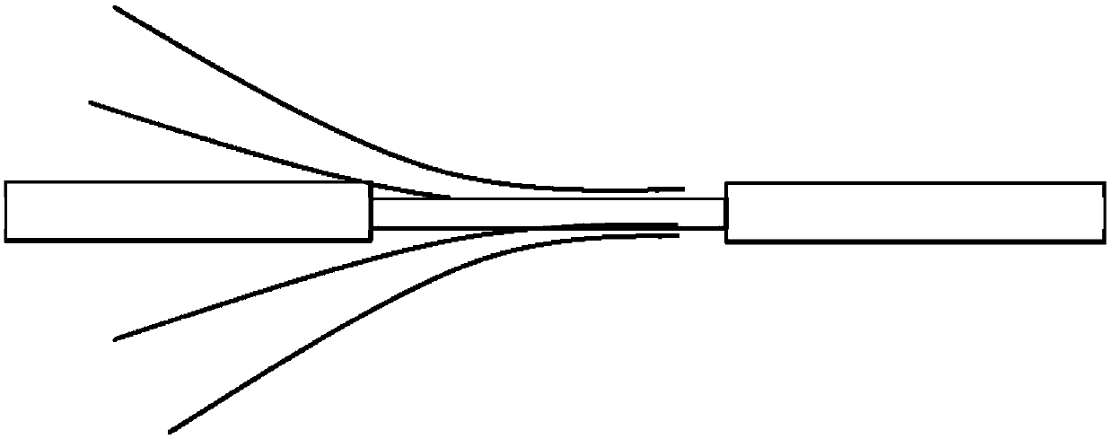
[0052] Such as figure 2 As shown, a side-pump signal combiner includes a main signal fiber and at least one side-arm input fiber. (two side arms are shown in the picture)

[0053] The main signal fiber has at least two layers of waveguide structure, the refractive index of the inner waveguide structure must be higher than that of the outer waveguide structure, and the main signal fiber is required to be a multimode fiber for the laser of the transmission wavelength.

[0054] The main signal fiber preferably has a two-layer waveguide structure, the outer waveguide structure is the cladding, and the inner waveguide structure is the core. The specific parameters can be selected from any of the following:

[0055]

[0056] The side arm input fiber preferably has a two-layer waveguide structure, the outer waveguide structure is the cladding, and the inner waveguide structure is the core. The specific parameters can be selected from any of the following:

[0057]

[0058] T...

Embodiment 2

[0064] Both the main signal fiber and the side arm signal fiber have a two-layer waveguide structure, the main signal fiber is 50 / 400, NA: 0.15 / 0.46, and the side arm input fiber is 50 / 125, NA: 0.12;

[0065] Using oxyhydrogen flame as heating source;

[0066] Side arm input fiber pretreatment: taper the side arm input fiber, and the diameter of the taper after the taper is 50 μm;

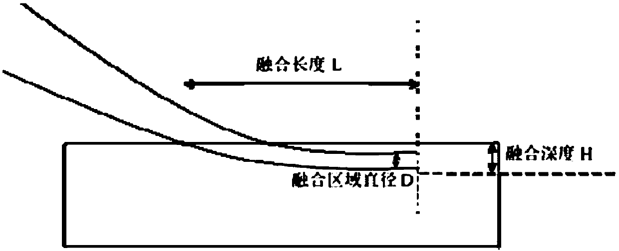
[0067] Bonding of the side arm input fiber and the main signal fiber: the main signal fiber and the side arm input fiber are fixed with a special clamp after the coating layer is stripped, and the side arm input fiber is stretched and fitted on the surface of the main signal fiber while the fiber does not deform or drop , fusion length L=2mm;

[0068] Side fusion of the side arm input fiber and the main signal fiber: control the fusion depth of the side arm input fiber and the main signal fiber by controlling the temperature of the oxyhydrogen flame and the length of the fusion time, and the fusio...

Embodiment 3

[0072] Both the main signal fiber and the side arm signal fiber have a three-layer waveguide structure, the main signal fiber is 50 / 70 / 660, NA:0.22, and the side arm input fiber is 100 / 120 / 360, NA:0.22;

[0073] Using oxyhydrogen flame as heating source;

[0074] Side arm input fiber pretreatment: taper the side arm input fiber, and the diameter of the taper after the taper is 100 μm;

[0075] Bonding of the side arm input fiber and the main signal fiber: the main signal fiber and the side arm input fiber are fixed with a special clamp after the coating layer is stripped, and the side arm input fiber is stretched and fitted on the surface of the main signal fiber while the fiber does not deform or drop , fusion length L=5mm;

[0076] Side fusion of the side arm input fiber and the main signal fiber: control the fusion depth of the side arm input fiber and the main signal fiber by controlling the temperature of the oxyhydrogen flame and the length of the fusion time, and the f...


PUM

PropertyMeasurementUnit
diameteraaaaaaaaaa
diameteraaaaaaaaaa
diameteraaaaaaaaaa

Abstract

The invention discloses a side pump signal beam combiner for realizing flat-topped beams and a preparation method thereof, and belongs to the technical field of laser beam shaping. The main signal optical fiber has at least two layers of waveguide structures; the refractive index of the inner-layer waveguide structure is higher than that of the outer-layer waveguide structure; the main signal optical fiber is a multimode optical fiber for laser with a transmission wavelength, the side arm input optical fiber is subjected to fused biconical taper processing to be attached to the interior of a waveguide structure outside the innermost layer waveguide structure of the main signal optical fiber, and the fusion length L of the side arm input optical fiber is 0 mm (L is smaller than or equal to200 mm; the fusion depth H is 0 [mu] m (H is less than or equal to 500 [mu] m; the diameter D of the fusion area is larger than or equal to 5 micrometers and smaller than or equal to 500 micrometers,the optical waveguide mode that signal light in the side arm input optical fiber enters the main signal optical fiber is changed by controlling the tapering fusion length, diameter and depth of the side arm input optical fiber, and therefore output of flat-topped mode light spots is achieved in the main signal optical fiber.

Description

technical field [0001] The invention relates to the technical field of laser beam shaping, in particular to a side-pump signal beam combiner for realizing a flat-hat beam and a preparation method thereof. Background technique [0002] The laser beam is generally a Gaussian beam, and the Gaussian beam has a high intermediate intensity, and the intensity in the radial direction gradually decreases along the Gaussian profile. The top-hat beam concept is a laser beam with a uniform distribution of light intensity. In a high-power and high-energy system, most of the energy of the Gaussian beam is concentrated in the central part, which is easy to damage the optical device. At the same time, the Gaussian beam will bring non-uniform heating to the device and affect the beam quality. In practical applications, the Gaussian beam is very easy to penetrate the material due to the high central light intensity. When the flat-top beam is used for laser engraving, the light intensity is u...

Claims


Application Information

Patent Timeline
Patent Type & Authority Applications(China)
IPC IPC(8): G02B27/09G02B6/028
CPCG02B27/0927G02B27/0994G02B6/0288
Inventor 李骁军李文涛张蕴川严超
Owner 江苏睿赛光电科技有限公司
Why Eureka
Try Eureka