Interestingness method and system based on eyeball steering

An eyeball and determination method technology, applied in the field of computer vision, can solve problems such as insufficient accuracy, inability to reflect the correlation and continuity of pictures and pictures, video association, etc., and achieve the effect of improving accuracy

Pending Publication Date: 2020-06-30
ONE CONNECT SMART TECH CO LTD SHENZHEN
View PDF5 Cites 3 Cited by
  • Summary
  • Abstract
  • Description
  • Claims
  • Application Information

AI Technical Summary

Problems solved by technology

It does not correlate the relationship between videos, and cannot reflect th...

Method used


Image

  • Interestingness method and system based on eyeball steering
  • Interestingness method and system based on eyeball steering
  • Interestingness method and system based on eyeball steering

Examples


Embodiment 1

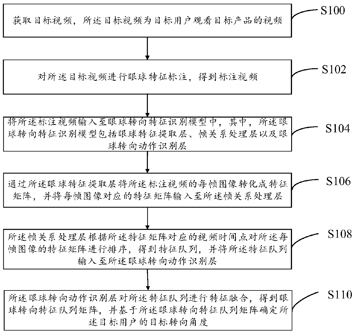
[0056] refer to figure 1 , shows a flow chart of the steps of the video-based eyeball turning determination method according to Embodiment 1 of the present invention. It can be understood that the flowchart in this method embodiment is not used to limit the sequence of execution steps. An exemplary description is given below taking the computer device 2 as the execution subject. details as follows.

[0057]Step S100, acquiring a target video, where the target video is a video of a target product watched by a target user.

[0058] Specifically, the process of the target user watching the target product is captured by the camera to obtain the target video, and the target video is transmitted to the computer device 2 for processing.

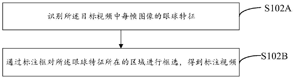
[0059] Step S102 , mark the target video with eyeball features to obtain the marked video.

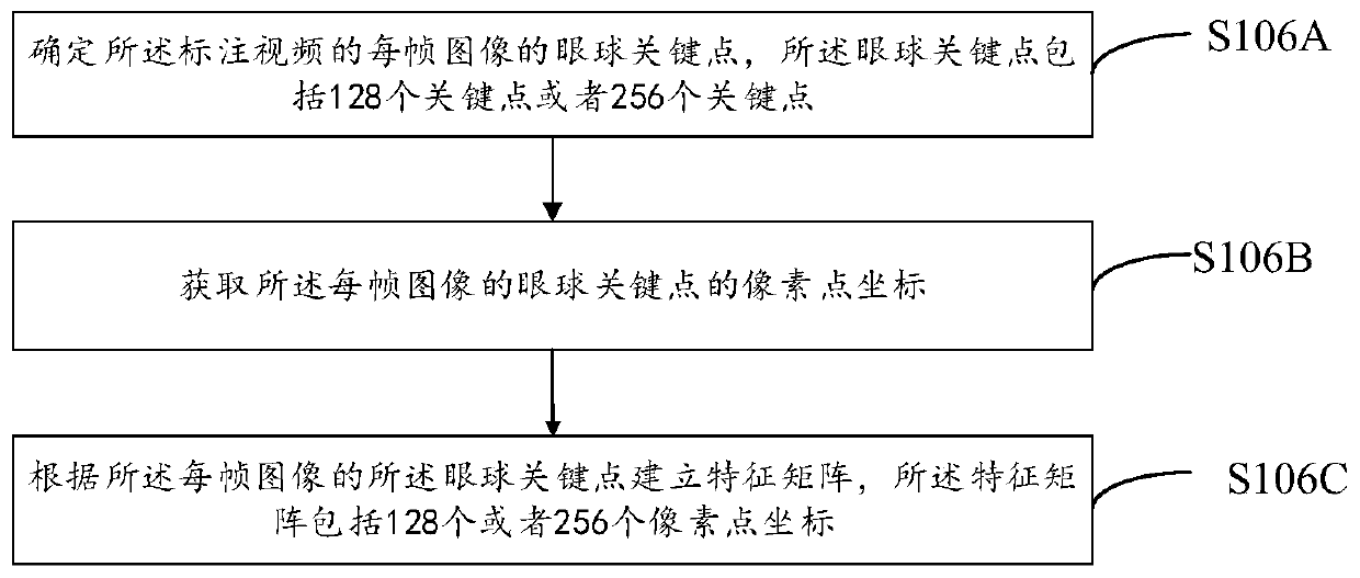
[0060] Specifically, each frame image of the target video is processed by image segmentation, object detection, picture annotation, etc., to obtain anno...

Embodiment 2

[0110] read on Figure 8 , shows a schematic diagram of program modules of Embodiment 2 of the video-based eyeball turning determination system of the present invention. In this embodiment, the video-based eyeball turning determination system 20 may include or be divided into one or more program modules, and one or more program modules are stored in a storage medium and executed by one or more processors , to complete the present invention, and realize the above video-based method for determining eyeball turning. The program module referred to in the embodiment of the present invention refers to a series of computer program instruction segments capable of accomplishing specific functions, which is more suitable than the program itself to describe the execution process of the video-based eyeball turning determination system 20 in the storage medium. The following description will specifically introduce the functions of each program module of the present embodiment:

[0111] T...

Embodiment 3

[0158] refer to Figure 9 , is a schematic diagram of the hardware architecture of the computer device according to Embodiment 3 of the present invention. In this embodiment, the computer device 2 is a device capable of automatically performing numerical calculation and / or information processing according to preset or stored instructions. The computer device 2 may be a rack server, a blade server, a tower server or a cabinet server (including an independent server, or a server cluster composed of multiple servers) and the like. like Figure 9 As shown, the computer device 2 at least includes, but is not limited to, a memory 21 , a processor 22 , a network interface 23 , and a video-based eyeball turning determination system 20 that can communicate with each other through a system bus. in:

[0159] In this embodiment, the memory 21 includes at least one type of computer-readable storage medium, and the readable storage medium includes flash memory, hard disk, multimedia card...


PUM


Abstract

The invention discloses a video-based eyeball turning determination method, and the method comprises the steps: obtaining a target video which is a video of a target user watching a target product; inputting the target video into an eyeball steering feature recognition model to obtain an eyeball steering feature queue matrix; and determining a target steering angle of the target user based on theeyeball steering characteristic queue matrix. The invention further discloses an eyeball steering determination system based on the video. According to the invention, the target video is input to theeyeball steering characteristic recognition model to obtain the eyeball steering characteristic queue matrix, and then the target steering angle and the target steering time of the corresponding target product are obtained through the eyeball steering characteristic queue matrix, so that the eyeball tracking accuracy is improved.

Description

technical field [0001] Embodiments of the present invention relate to the technical field of computer vision, and in particular to a method and system for determining eye movement based on video. [0002] technical background [0003] Human eye tracking has long been used to study individual visual attention, and the most commonly used eye tracking technology is pupil center corneal reflection (pupil center corneal reflection (PCCR)). The principle of PCCR technology is that, captured by the camera of the physical tracking device, the light source illuminates the pupil to form a highly visible reflected image. These images will be used to determine the reflection of the light source in the cornea and pupil, and finally through the cornea and pupil reflection. The vector angle is calculated with other geometric features to obtain the direction of human gaze. However, this scheme has a large correlation with the light source, and there are many interference factors, so the ide...

Claims


Application Information

Patent Timeline
IPC IPC(8): G06K9/00G06F3/01
CPCG06F3/013G06V40/193
Inventor 卢宁徐国强
Owner ONE CONNECT SMART TECH CO LTD SHENZHEN
Why Eureka
Try Eureka