Magnetic assembly and power supply module

A technology of magnetic components and power modules, which is applied in the field of power electronics, can solve the problems of poor heat dissipation of magnetic components, achieve the effects of reducing thermal resistance, improving heat dissipation, and shortening heat dissipation paths

Pending Publication Date: 2020-06-30
DELTA ELECTRONICS (SHANGHAI) CO LTD
View PDF7 Cites 4 Cited by
  • Summary
  • Abstract
  • Description
  • Claims
  • Application Information

AI Technical Summary

Problems solved by technology

[0005] Embodiments of the present invention provide a magnetic component and a power module to solve the problem of poor heat dissipation of the magnetic component

Method used


Image

  • Magnetic assembly and power supply module
  • Magnetic assembly and power supply module
  • Magnetic assembly and power supply module

Examples


Embodiment 1

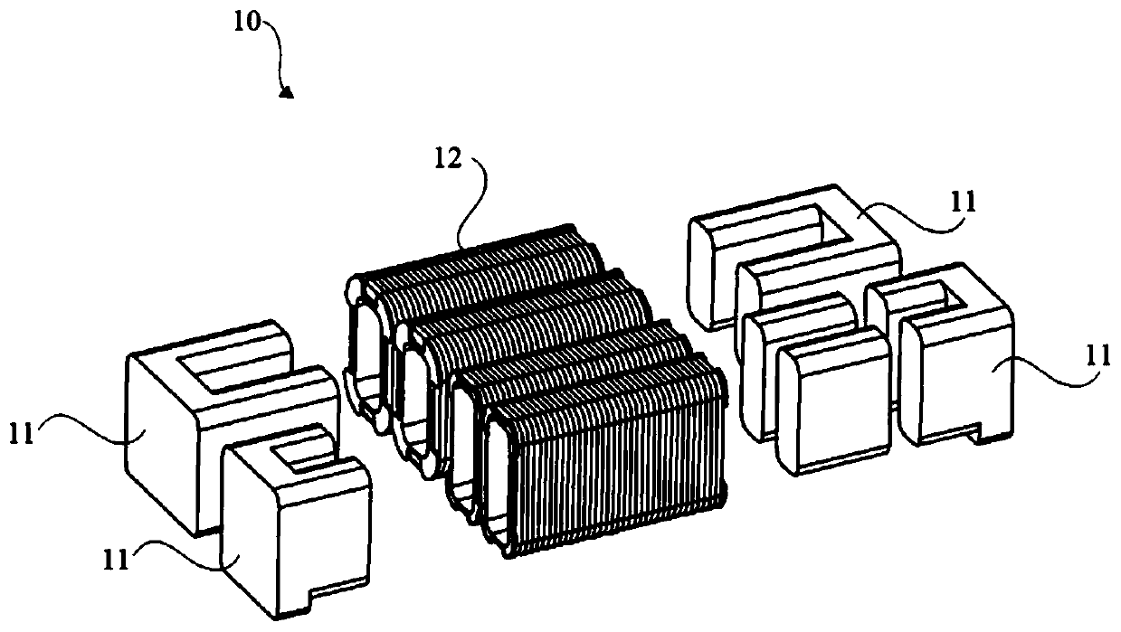
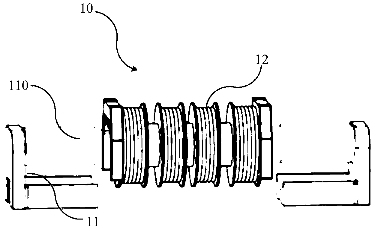
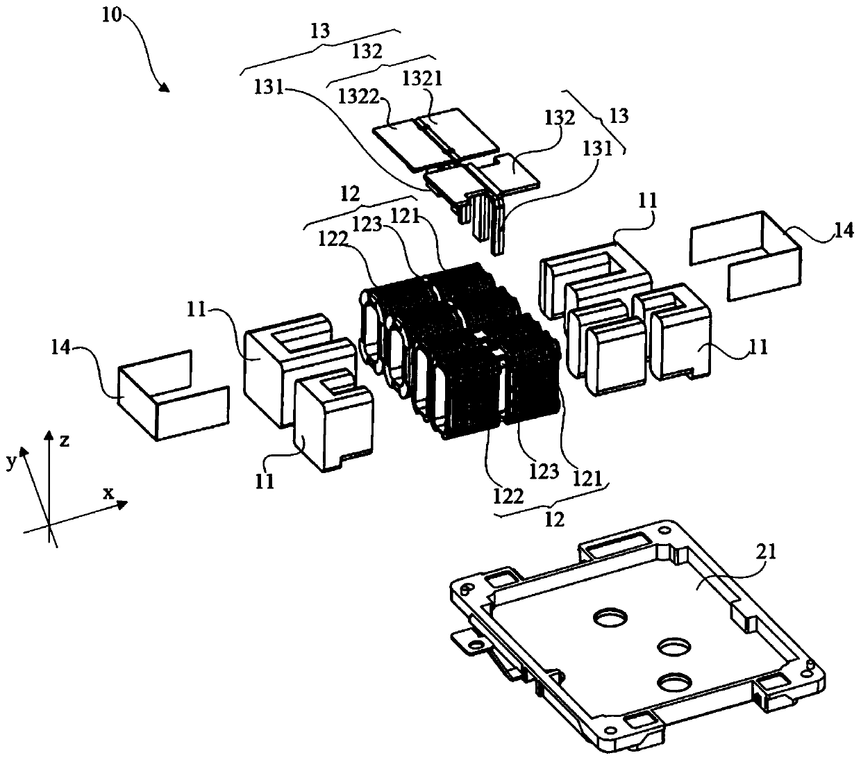
[0087] figure 2 It is a schematic diagram of a disassembled structure of a magnetic assembly provided in Embodiment 1 of the present invention, image 3 It is an overall assembly diagram of a magnetic assembly provided in Embodiment 1 of the present invention, Figure 4 It is a schematic cross-sectional view of a magnetic assembly provided in Embodiment 1 of the present invention. see Figure 2 to Figure 4 , the present embodiment provides a magnetic assembly 10 , the magnetic assembly 10 includes a first heat dissipation structure 13 , a magnetic core 11 extending in a transverse direction, and a winding structure 12 wound on the magnetic core 11 . Wherein, the winding structure 12 at least includes a first winding package 121 and a second winding package 122 arranged adjacently in the transverse direction, and there is a gap 123 between the first winding package 121 and the second winding package 122, at least part of the first heat dissipation structure 13 is disposed i...

Embodiment 2

[0102] see Figure 2 to Figure 4 , on the basis of Embodiment 1, in this embodiment, the magnetic assembly 10 also includes two U-shaped (or L-shaped, not shown) second heat dissipation structures 14, one of the second heat dissipation structures 14 is inserted between the magnetic core 11 and the first winding package 121 along the transverse direction; specifically, the opening of one of the second heat dissipation structures 14 faces the magnetic core 11, and is inserted into the magnetic core 11 and the first winding package 121 along the transverse direction. Between the winding packages 121 , in other words, the open end of one of the U-shaped second heat dissipation structures 14 is inserted into the magnetic core 11 , and is arranged between the magnetic core 11 and the first winding package 121 . Another second heat dissipation structure 14 is inserted between the magnetic core 11 and the second winding package 122 along the transverse direction; that is, another U-sh...

Embodiment 3

[0108] Image 6 It is a schematic diagram of a disassembled structure of a magnetic assembly provided by Embodiment 3 of the present invention. On the basis of Embodiment 1, in this embodiment, the magnetic assembly 10 also includes two T-shaped (or L-shaped, not shown) As shown), the magnetic core 11 includes a first sub-core 111 and a second sub-core 112 stacked along the vertical direction. Specifically, such as Image 6 As shown, the magnetic core 11 is divided into a first sub-core 111 and a second sub-core 112 stacked up and down along the vertical direction, and the second heat dissipation structure 14 is T-shaped. One of the second heat dissipation structures 14 is inserted between the first sub-core 111 and the second sub-core 112 from the first side of the magnetic core 11 along the lateral direction. Specifically, the T-shaped second heat dissipation structure 14 is inserted into the inner side of the magnetic core 11 from the left side of the magnetic core 11, an...


PUM

PropertyMeasurementUnit
thermal conductivityaaaaaaaaaa

Abstract

The invention provides a magnetic assembly and a power supply module and relates to the technical field of power electronics. The magnetic assembly comprises a first heat dissipation structure, a magnetic core extending in the transverse direction and a winding structure arranged on the magnetic core in a winding mode. The winding structure at least comprises a first winding package and a second winding package which are adjacently arranged in the transverse direction. A gap is formed between the first winding package and the second winding package; at least a part of the first heat dissipation structure is arranged in the gap; the first heat dissipation structure is in thermal contact with the first winding package, the second winding package and the magnetic core such that the first heatdissipation structure can help the magnetic core, the first winding package and the second winding package dissipate heat in the vertical direction and the longitudinal direction at the same time, the heat dissipation path is shortened, the thermal resistance is reduced, and the heat dissipation effect of the magnetic assembly is improved.

Description

technical field [0001] The invention relates to the technical field of power electronics, in particular to a magnetic component and a power module. Background technique [0002] With the continuous development of switching power supply technology and the continuous development of various new energy power generation and electrical equipment, high-power power supply modules have become an obvious direction of development and demand; and with the increasing power demand, how to The heat dissipation of the magnetic components in the power module has become a research hotspot. [0003] The magnetic component may be a transformer or an inductor, which generally includes a magnetic core and multiple winding packages arranged on the magnetic core. The heat generated inside the magnetic component mainly comes from the heating of the magnetic core and the winding packages. The heat generated by the magnetic components is often dissipated by using a liquid-cooled heat dissipation cavi...

Claims


Application Information

Patent Timeline
Patent Type & Authority Applications(China)
IPC IPC(8): H01F27/08H01F27/22H01F27/24H01F27/28H01F27/30
CPCH01F27/08H01F27/22H01F27/24H01F27/2876H01F27/306H01F3/10H01F27/025H02M3/33584H02M1/0064H02M1/327H02M3/003H02M3/01H02M3/33573Y02T10/70Y02T10/7072Y02T90/14B60L53/122H01F27/325
Inventor 刘诗威常磊杨海军卢增艺章进法
Owner DELTA ELECTRONICS (SHANGHAI) CO LTD
Why Eureka
Try Eureka