Eureka AIR delivers breakthrough ideas for toughest innovation challenges, trusted by R&D personnel around the world.

Antenna oscillator and manufacturing method thereof

A manufacturing method and vibrator technology, applied to antennas, antenna parts, antenna supports/installation devices, etc., can solve problems such as directional deviation and failure to meet antenna performance requirements, and achieve the effect of enhancing the bonding strength

Active Publication Date: 2020-06-30
深圳慧联达科技有限公司
View PDF9 Cites 2 Cited by
  • Summary
  • Abstract
  • Description
  • Claims
  • Application Information

AI Technical Summary

Problems solved by technology

[0003]Traditional sheet metal and die-casting antenna vibrator, limited by the precision of the process, is prone to directional deviation, which can no longer meet the performance requirements of the antenna

Method used


Image

  • Antenna oscillator and manufacturing method thereof
  • Antenna oscillator and manufacturing method thereof
  • Antenna oscillator and manufacturing method thereof

Examples


Embodiment Construction

[0068] In order to make the object, technical solution and advantages of the present invention clearer, the present invention will be described in further detail below in conjunction with specific embodiments and with reference to the accompanying drawings. However, those skilled in the art know that the present invention is not limited to the drawings and the following embodiments.

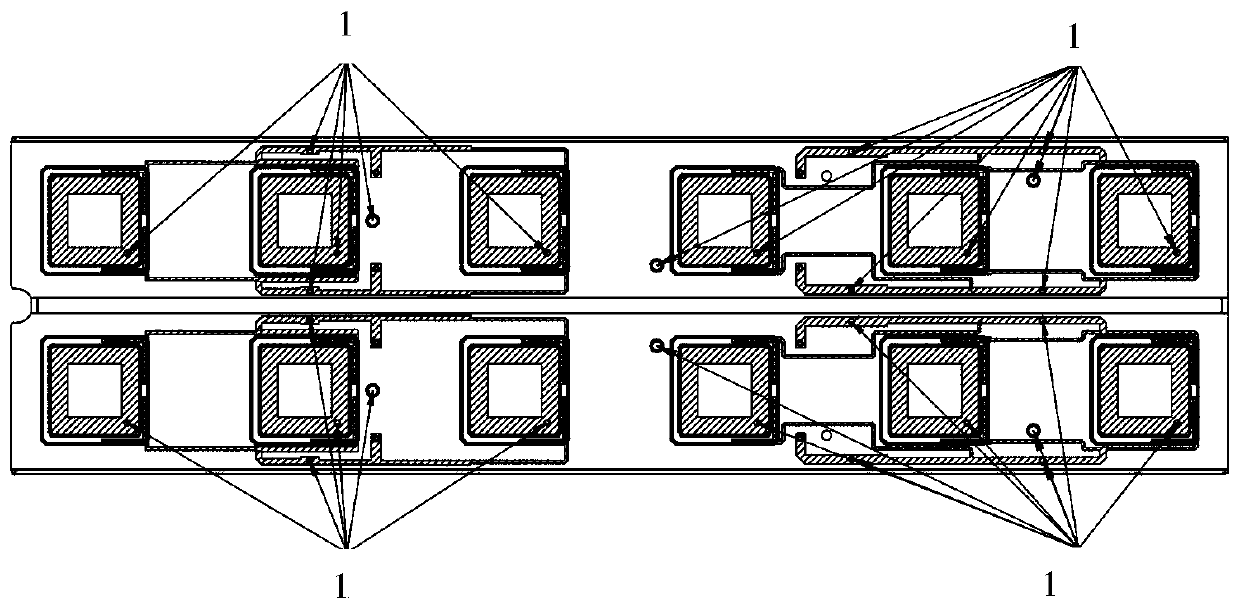
[0069] Such as figure 1 , set multiple rack plating holes 1 in the metal plating area. The rack plating holes are set on a wider network. The current balance must be considered. The rack plating holes should be as far away from the slender network as possible. The recommended diameter of the rack plating holes is 1.6mm. For a large-area plating area, the diameter of the rack plating hole should be appropriately increased, which is 3.1mm in this case.

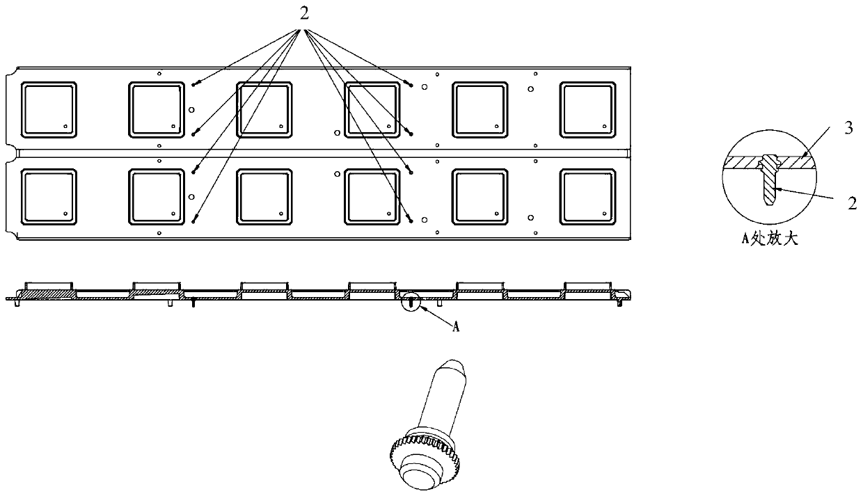
[0070] Such as figure 2 The material of the feeder needle 2 is lead brass, and the head is knurled to increase the bonding force between the f...


PUM

PropertyMeasurementUnit
thicknessaaaaaaaaaa
thicknessaaaaaaaaaa
pore sizeaaaaaaaaaa

Abstract

The invention relates to a manufacturing method of a plastic oscillator. According to the method, due to the change of the annealing mode, the oscillator body obtained by injection molding is high inflatness; the combination degree with the reflecting plate is improved; due to the optimization of the roughening process, the stripping resistance of the electroplated layer of the oscillator body ishigh, the bonding force and the damage resistance of the oscillator body and the reflecting plate are obviously improved due to the improvement of the structure of the feed pin for communicating theoscillator body and the reflecting plate, the reliability and the stability of the product are greatly improved through the measures, and the high requirement of product performance is met. On the other hand, the flatness of the oscillator body is improved, and the electrical property of the antenna oscillator is obviously improved through the arrangement of the rack plating holes. In addition, according to the method, the existing process is simplified, the cost is saved, and the product form is further generated and manufactured in a module form.

Description

technical field [0001] The invention belongs to the technical field of communication equipment, and in particular relates to an antenna vibrator and a manufacturing method thereof. Background technique [0002] With the advent of the 5G communication era, the upsurge of multi-frequency communication and ultra-wideband communication technology research has come, and the flat reflector antenna as a base station antenna plays a vital role in improving communication quality. Usually it includes the radiation unit - the vibrator or vibrator array, power division network (feed network), metal flat reflector (reflector), calibration network and other components. As an integral part of the base station antenna, the vibrator directly affects the base station Antenna performance. [0003] Traditional sheet metal and die-casting antenna oscillators are limited by the precision of the process, and are prone to directional deviations, which can no longer meet the antenna performance req...

Claims


Application Information

Patent Timeline
Patent Type & Authority Applications(China)
IPC IPC(8): H01Q1/36H01Q1/50H01Q1/24H01Q19/10B29C45/00C23C18/38C25D3/30C25D3/38C25D5/02C25D5/10C25D5/56C25D7/00
CPCH01Q1/36H01Q1/246H01Q19/10H01Q1/50C23C18/38C25D5/02C25D3/38C25D3/30C25D5/56C25D7/00C25D5/10B29C45/00
Inventor 黄飞谢咏君冯彬
Owner 深圳慧联达科技有限公司
Why Eureka
Eureka Blog
Learn More